Optical add-drop multiplexer, and optical network equipment using the same

a technology of optical network equipment and multiplexers, applied in multiplex communication, transmission monitoring, electromagnetic repeaters, etc., can solve the problems of increased equipment cost, extra space for accommodating boards, and extra time until services are provided, so as to increase failure resistance, high functionality, and high cost

Inactive Publication Date: 2006-08-03
HITACHI LTD
View PDF3 Cites 53 Cited by
  • Summary
  • Abstract
  • Description
  • Claims
  • Application Information

AI Technical Summary

Benefits of technology

[0016] If the above 1+1 optical protection function and the above 1:1 optical protection function are used in combination, it becomes possible to achieve both of the optical protection functions in one kind of optical add-drop multiplexer.
[0020] In particular, the optical transceiver located in the above transmit / receive node can be realized as a smaller device with high modularity by configuring the optical transceiver as a two-output optical transmitters including a built-in 1:2 optical coupler, or as a two-input optical receiver including a 2:1 built-in coupler, or as a two-output two-input optical transceiver into which both of them are combined.
[0023] In particular, a matrix switch capable of mutually interchanging optical signals of a plurality of add signal fibers and those of a plurality of drop signal fibers, or optical couplers which branch an add signal fiber into a plurality of optical fibers and branch a drop signal fiber into a plurality of optical fibers, are located in each optical add-drop multiplexer. Then, by making a connection for either the span switch or the ring switch, or by making connections for both of them, it is possible to achieve the span switch and the ring switch at the same time, and further to achieve the optical protection in a generally used mesh optical network.
[0030] According to the present invention, it is possible to achieve the optical protection functions without using external active parts. In addition, it is possible to achieve the optical protection with high functionality, with high cost effect, with increased failure resistivity, and with high reliability. Moreover, very high-speed optical protection becomes possible.

Problems solved by technology

Therefore, the costs of equipment increase, and extra space for accommodating the boards is required, which are the main problems.
Moreover, if each signal line corresponding to each wavelength requires these functions, it is necessary to deliver the parts or boards required for the nodes 124-1, 124-2 that are several tens of kilometers away, and also to implement the parts or boards by an operator there, with the result that it takes extra time until services are provided.
However, such optical protection cannot be applied to another information traffic of a backup signal line, and cannot cope with a multiple failure, or the like.
Therefore, there are also the problems of low economical efficiency and low reliability.

Method used


Image

  • Optical add-drop multiplexer, and optical network equipment using the same
  • Optical add-drop multiplexer, and optical network equipment using the same
  • Optical add-drop multiplexer, and optical network equipment using the same

Examples


first embodiment

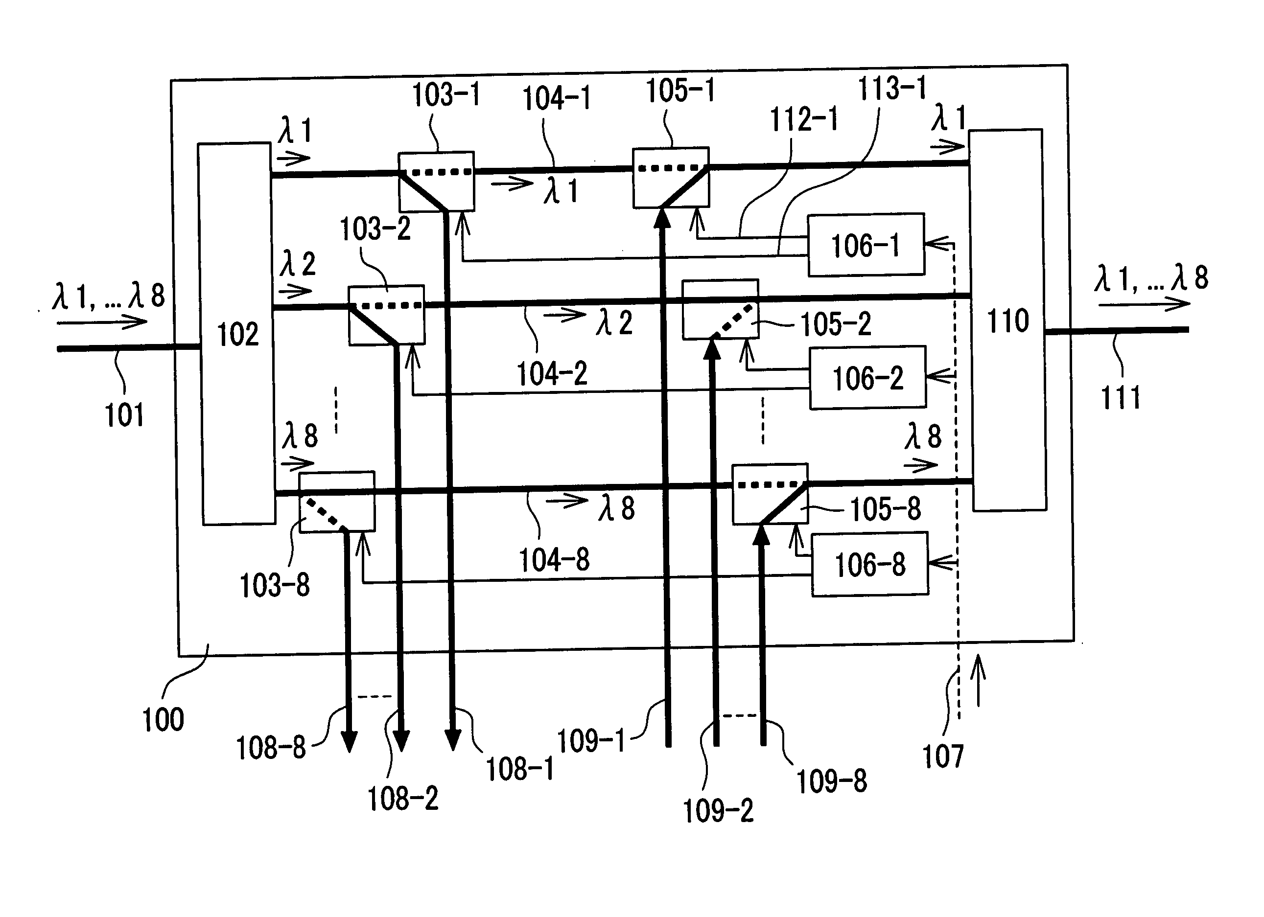
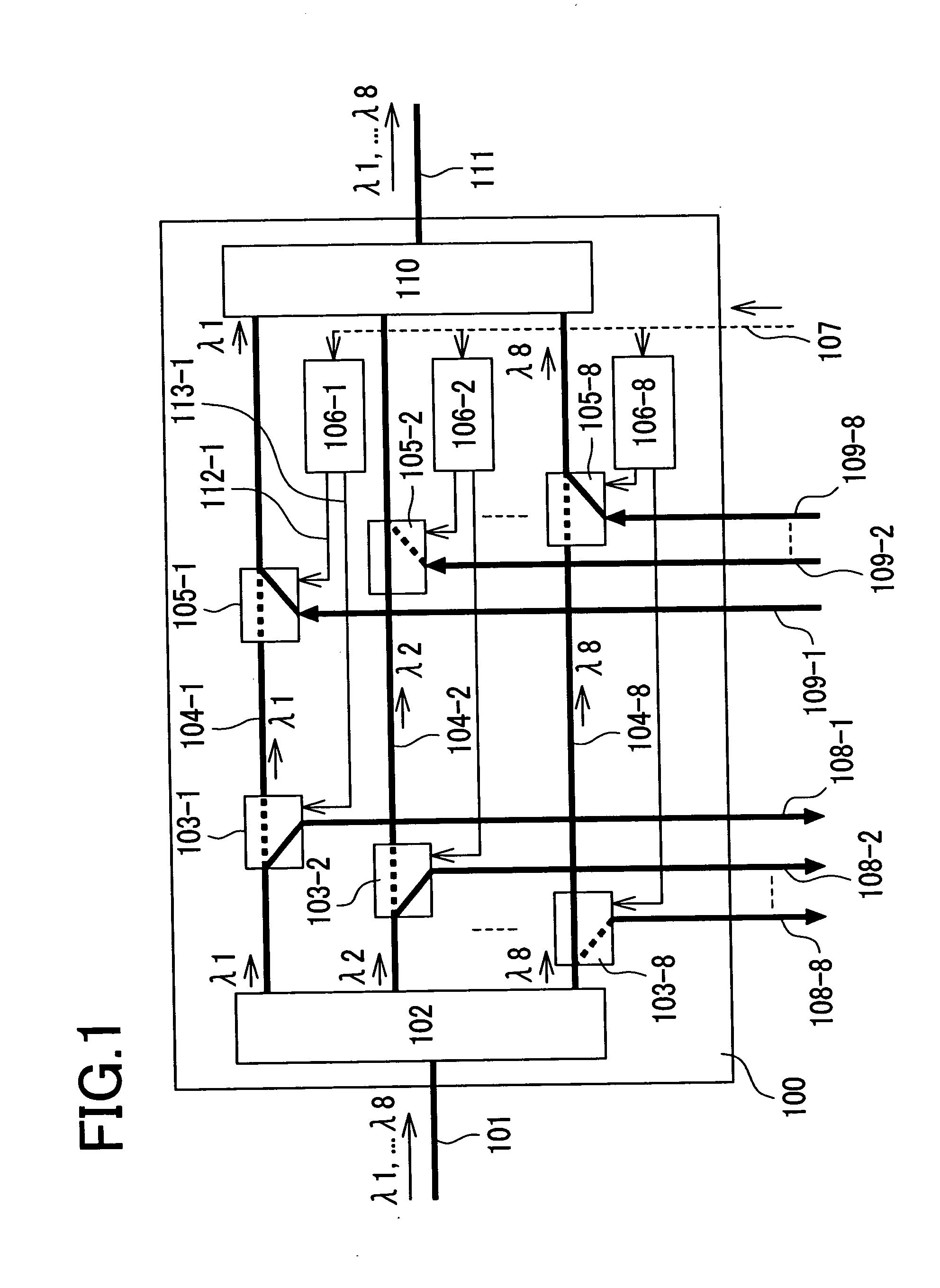
[0052]FIG. 1 is a schematic view illustrating a first embodiment according to the present invention. FIG. 1 illustrates an example of how an optical add-drop multiplexer (OADM) 100 according to the present invention is configured. The optical add-drop multiplexer 100 according to the present invention is located between an input WDM optical fiber line 101 and an output WDM optical fiber line 111. An inputted wavelength-division multiplexed signal having eight wavelengths λ1 through λ8 is separated and passed into through signal paths 104-1 through 104-8 on a wavelength basis by an optical wavelength demultiplexer 102. After that, the separated signals are wavelength-division multiplexed by an optical wavelength multiplexer 110 again, and this wavelength-division multiplexed signal is then output.

[0053] 1×2 optical switches (drop switches) 103-1 through 103-8 used to set a drop state of an optical signal, and 2×1 optical switches (add switches) 105-1 through 105-8 used to set an add...

second embodiment

[0071]FIG. 4 is a schematic view illustrating a second embodiment of the present invention. FIG. 4 illustrates the configuration of a node 124-1 in which a failure detection circuit 135 is built into an optical add-drop multiplexer according to the present invention, and in which a two-output two-input optical transceiver 138 is used. In this example, part of an optical signal corresponding to each wavelength output from the optical wavelength demultiplexers 102-1, 102-2 is dropped, and is then introduced into the failure detection circuit 135. Failure information of the active signal line, which has been detected by the active-side failure detection circuit 135-1 corresponding to the wavelength λ1, is branched into two. Then, both of the branched failure information are inputted into the active-side and backup-side optical switch control circuits 106-1, 106-2 corresponding to the wavelength λ1 respectively. Likewise, failure information of the backup signal line, which has been det...

third embodiment

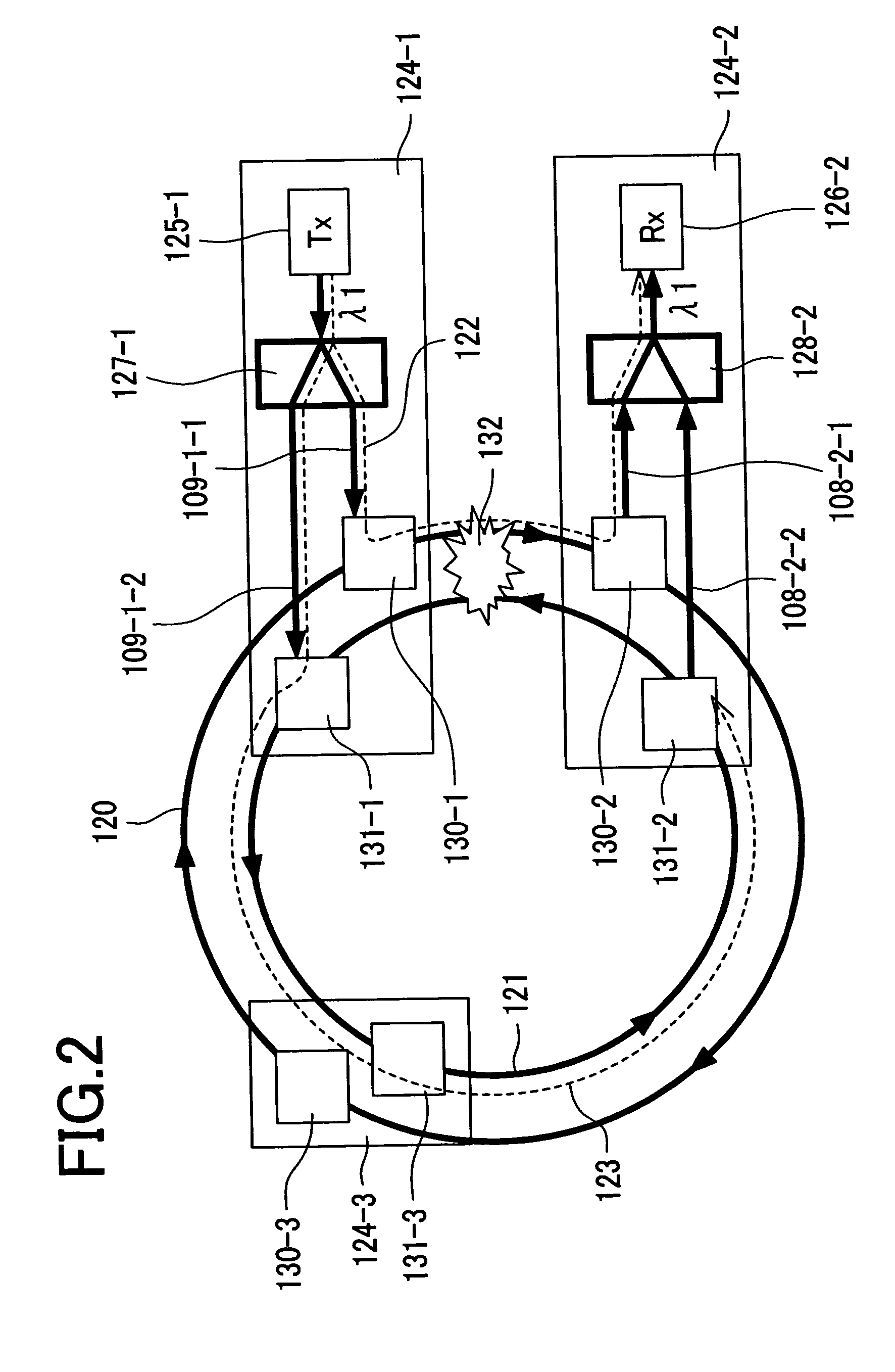
[0076]FIG. 8 is a diagram illustrating a third embodiment of the present invention. FIG. 8 illustrates an example in which 1:1 optical protection is implemented in a two-fiber ring network according to the present invention. The configuration in a transmission node 124-1-and that in a receiving node 125-1 are the same as the configuration of the 1+1 optical protection shown in FIG. 2. According to the present invention, it is possible to select an arbitrary optical protection mode if necessary by changing settings of software.

[0077] The 1:1 optical protection adopts a mode in which an optical signal is transmitted to only a normal optical fiber line on the transmission side. In a normal state, as shown in FIG. 19, an add switch corresponding to the wavelength λ1 in the active-side optical add-drop multiplexer 130-1 included in the transmission node 124-1 is set to an add state; and an add switch corresponding to the wavelength λ1 in the backup-side optical add-drop multiplexer 131-...


PUM


Abstract

Heretofore, it was necessary to individually locate an optical switch, an optical switch control circuit, and the like, before and after an optical transceiver that performs optical protection. As a result, costs and the space for implementation increase, and a delay in services is also caused, which were the problems. For the purpose of solving the above problems, the present invention provides a simple optical protection method used in an optical add-drop multiplexer. Add switches 105-1 through 105-N and drop switches 103-1 through 103-N for optical signals corresponding to each wavelength in an optical add-drop multiplexer 100 are made controllable independently of one another. Add switches and drop switches of the active-side and backup-side optical add-drop multiplexers are switched by optical switch control circuits 106-1 through 106-N respectively to make a detour around a failure so that the optical protection is achieved.

Description

CLAIM OF PRIORITY [0001] The present application claims priority from Japanese application JP2005-024840, filed on Feb. 1, 2005, the content of which is hereby incorporated by reference into this application. BACKGROUND OF THE INVENTION [0002] 1. Field of the Invention [0003] The present invention relates to an optical add-drop multiplexer, and optical network equipment using the same, and more particularly to transmission of optical information by use of optical fibers. [0004] 2. Description of Related Art [0005] The wavelength division multiplexed (WDM) optical transmission method is a very effective method for increasing the capacity of optical fiber communications. In this method, a plurality of optical signals whose wavelengths differ from one another are multiplexed into one optical fiber to transmit information. An optical add-drop multiplexer (OADM) is a kind of transmission equipment placed at each node in an optical fiber network that carries a wavelength division multiple...

Claims


Application Information

Patent Timeline
Patent Type & Authority Applications(United States)
IPC IPC(8): H04J14/02H04B10/03H04B10/032H04B10/27H04B10/275H04B10/29H04J14/00
CPCH04J14/0206H04J14/0212H04J14/0227H04J14/0283H04J14/0284H04J14/0286H04J14/0294H04J14/0295H04J14/0246H04J14/025
Inventor KIKUCHI, NOBUHIKO
Owner HITACHI LTD
Why Eureka
Try Eureka