Optical control device and optical control method

a control device and optical control technology, applied in the direction of fluorescence/phosphorescence, instruments, polarising elements, etc., can solve the problems of large apparatus, difficult simultaneous control of spatial light intensity distribution and temporal laser beam waveform, and difficulty in changing many kinds of color characteristics

Inactive Publication Date: 2006-08-10
KAWASAKI HEAVY IND LTD
View PDF1 Cites 29 Cited by
  • Summary
  • Abstract
  • Description
  • Claims
  • Application Information

AI Technical Summary

Benefits of technology

[0075] The optical control method of the present invention can be applied to various illuminating methods, light sources for displays and process control methods by using the effect of combination of the wavelength components respectively having different spatial distributions.

Problems solved by technology

The method of providing light waves of different color characteristics by using a plurality of light sources, individually modulating the intensities of light waves and mixing the intensity-modulated light waves needs a complicated apparatus.
The method using the color filters has difficulty in changing many kinds of color characteristics.
However, it has been difficult to control spatial light intensity distribution and temporal pulse waveform simultaneously.
Particularly, in a region of control where the response speed limit of liquid crystal is on the order of microseconds, the simultaneous control of the spatial light intensity distribution and temporal laser beam waveform needs a large, complicated apparatus and is very difficult.
Thus those methods have a low degree of freedom of optical adjustment and cannot give different light intensity distribution patterns to the wavelength components.
This method, however, cannot adjust the spatial light intensity distribution and hence cannot provide a laser beam that enables processing of a high degree of freedom using wavelengths of different light intensities.
However, such an optical system is large and complicated.
None of the light modulators based on the prior art derives various color characteristics from a light source and gives desired spatial light intensity distributions for a plurality of different wavelength components.
There has not been any means for giving different spatial light intensity distributions for wavelength components at a time difference of milliseconds.
When it is desired to control a temporal characteristic and a spatial characteristic simultaneously, as regards an ultrashort light pulse temporal region, the response speed of the known method using the spatial light modulator employing the liquid crystal or the known method using the deformable mirror is not sufficiently high.
Thus, problems in the dimensions, efficiency and costs of the optical system make the practical application of the optical system impossible.

Method used


Image

  • Optical control device and optical control method
  • Optical control device and optical control method
  • Optical control device and optical control method

Examples


first embodiment

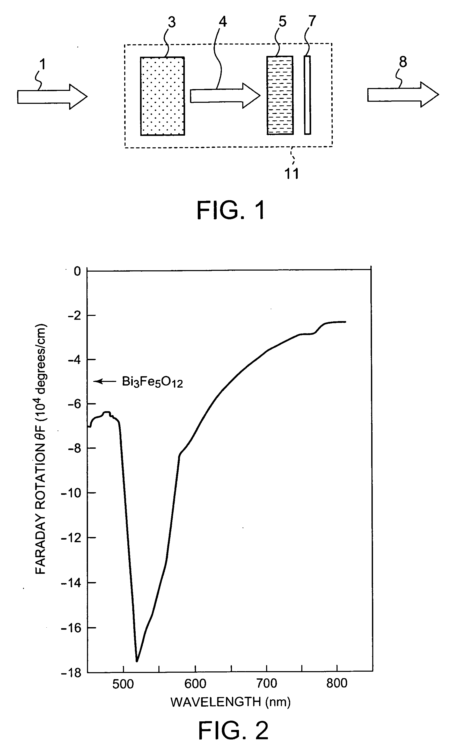
[0119] An optical control system 11 in a first embodiment according to the present invention receives an incident linearly polarized light wave containing a plurality of wavelength components, passes the linearly polarized light wave through an optical rotatory dispersion device to change the polarization plane rotation angles of the wavelength components, passes the linearly polarized light wave through an analyzer, and obtain a light wave containing wavelength components respectively having different spatial light intensity distributions by a spatial light modulator including a polarization plane rotator, such as a liquid crystal.

[0120] Referring to FIG. 1, the optical control system 11 includes a wavelength dispersion type optical rotatory device 3, an analyzer 7 and a spatial light modulator 5 capable of giving an optional polarization angle spatial distribution to the polarization plane of the incident light wave.

[0121] The analyzer 7 is an optical element that transmits a po...

second embodiment

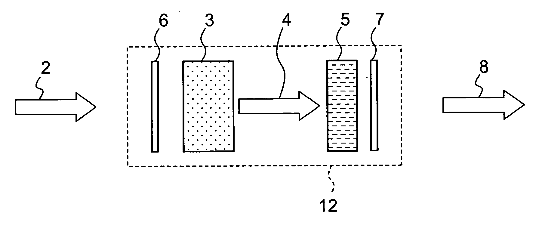
[0162] An optical control system 13 in a second embodiment according to the present invention is provided with a wavelength phase modulator 17 in addition to components corresponding to those of the optical control system 11. The optical control system 13 adjusts, in addition to spatial light intensity distributions of wavelength components, the temporal waveform or phases of wavelength components of an incident light wave to emit a desired outgoing light wave.

[0163] Referring to FIG. 19 schematically showing the optical control system 13 in the second embodiment, the optical control system 13 adjusts the phases of the wavelength components of an incident linearly polarized light wave 1 so as to meet a predetermined relation by the wavelength phase modulator 17, changes the polarization plane rotation angles of the wavelength components by an azimuth rotator 3 having an optical rotatory dispersion characteristic, and then passes the incident linearly polarized light wave 1 processe...

third embodiment

[0177] An optical control system 51 in a third embodiment according to the present invention forms a desired far field pattern by adjusting a near field phase distribution by using a spatial light modulator capable of controlling spatial optical phase to achieve laser process control.

[0178] Referring to FIG. 23 showing the optical control system 51, the optical control system 51 has a wavelength dispersion type optical rotatory device 3 capable of changing optical rotation angle according to wavelength and a spatial optical phase modulator 52. An incident light wave 1 passes through the optical rotatory device 3 and the spatial optical phase modulator 52 in that order.

[0179] The spatial optical phase modulator 52 produces an outgoing light wave 53 differing in the ratio between a polarized component to be subjected to spatial optical phase modulation and a polarized component not to be subjected to spatial optical phase modulation from a light wave having a different polarization ...


PUM

PropertyMeasurementUnit
velocityaaaaaaaaaa
wavelengthaaaaaaaaaa

Abstract

An optical control system receives an incident light wave containing a plurality of wavelength components and is capable of giving different spatial light intensity distributions respectively to the wavelength components and of easily changing the color characteristic of an outgoing light wave. The optical control system is applied to illumination systems and light sources for displays, and to a method and an apparatus for process control using such modulated light. The optical control system receives a linearly polarized light wave as an incident light wave 1 containing a plurality of wavelength components, gives different polarization plane rotation angles respectively to the wavelength components by a wavelength dispersion azimuth rotator 3, gives the plane of polarization of the incident light wave 1 an optional optical rotation angle spatial distribution by a spatial light modulator 5, and emit an outgoing light wave containing wavelength components respectively having different spatial light intensity distributions by an analyzer 7.

Description

TECHNICAL FIELD [0001] The present invention relates to a new spatial light modulating system capable of giving different spatial light intensities respectively to the component waves of incident light and of readily changing the color characteristic of outgoing light, to the application of the spatial light modulating system to illumination systems and light sources for displays, and to a method and an apparatus for process control using such modulated light. BACKGROUND ART [0002] Techniques for changing the color characteristic of light emitted by a light source can be applied not only to illumination systems and light sources for displays but also to many uses including laser machining, laser plasma x-ray generation and laser fluorescent microscopes. It is expected that a method capable of providing many kinds of color characteristics in a wide spectral range can be applied to a wide variety of industrial fields. Known techniques provide light waves of different color characteris...

Claims


Application Information

Patent Timeline
Patent Type & Authority Applications(United States)
IPC IPC(8): G02B26/00G03H1/12G02B5/30G01N21/64G02B27/09G02B27/28G02F1/139
CPCG01N21/6458G02B27/288G02F1/139G02F2203/05G02F2203/12
Inventor MURO, MIKIOHAZAMA, HISANAOTAKATANI, YOSHIAKI
Owner KAWASAKI HEAVY IND LTD
Why Eureka
Try Eureka