
Process for applying a protective layer

a protective layer and process technology, applied in the direction of superimposed coating process, solid-state diffusion coating, coating, etc., can solve the problems of thermal conductivity and process has been extensively limited to low-aluminum starting layer, and achieve the effect of improving the oxidation resistance of simple mcraly layer acting as adhesive layer

Inactive Publication Date: 2006-08-10
MAN ENERGY SOLUTIONS SA
View PDF16 Cites 17 Cited by
  • Summary
  • Abstract
  • Description
  • Claims
  • Application Information

AI Technical Summary

Benefits of technology

[0008] The basic object of the present invention is to provide a process by means of which the oxidation resistance of simple MCrAlY layers acting as adhesive layers is improved by increasing the Al content of the MCrAlY layer without embrittlement taking place.
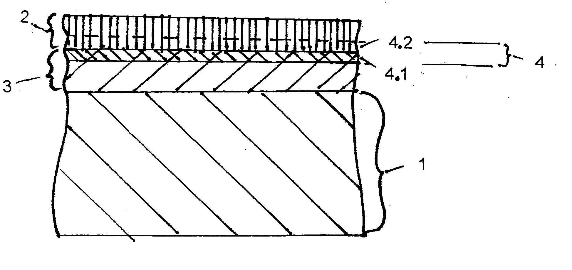
[0013] Due to the increase in the Al content in the simple MCrAlY layer because of the alitizing, the oxidation resistance of this layer acting as an adhesive layer is improved. The embrittlement on the surface of the alitized layer, which is caused by the alitizing, is prevented from occurring but at least minimized by the abrasive aftertreatment.
[0014] The service life of the heat insulation layers deposited by vapor deposition especially by means of an electron beam is considerably prolonged by the higher aluminum content. In case of premature failure of the heat insulation layer, e.g., due to the impact of foreign bodies or erosion, a longer “emergency operation” is possible. On the other hand, the risk of crack initiation is minimized by the removal of the especially brittle β-NiAl phase.
[0015] The alitizing of the adhesive layer and of the inner cooling channels of the component can be carried out simultaneously, so that there will be only slight extra costs for the blasting.

Problems solved by technology

Heat insulation systems always comprise a metallic adhesive layer connected with the base material (base metal) by diffusion and a superjacent ceramic layer with poor thermal conductivity, which is the actual barrier against the heat flow and protects the base metal against high-temperature corrosion and high-temperature erosion.
However, this process has hitherto been extensively limited to low-aluminum starting layers because of the risk of embrittlement.

Method used


Image

  • Process for applying a protective layer
  • Process for applying a protective layer

Examples


Embodiment Construction

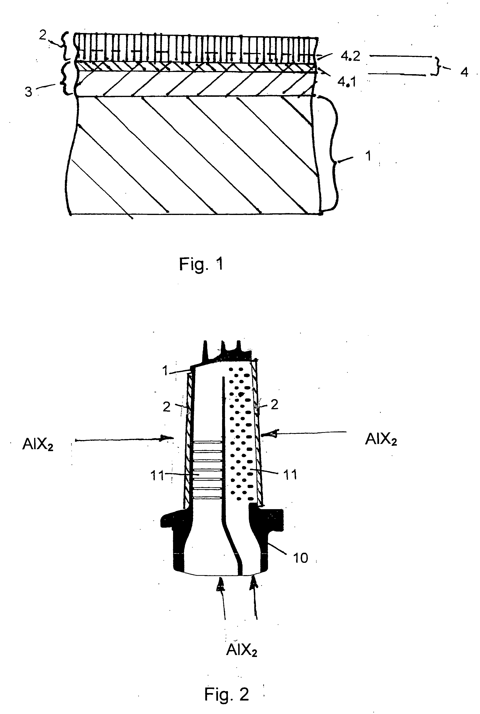
[0021] Referring to the drawings in particular, a gas turbine blade 10 according to FIG. 2 is of a hollow design and has cooling channels 11 on the inside.

[0022] A base metal layer 1, which may be the base material for the blade 10 of the gas turbine or even for another component of a gas turbine that comes into contact with hot gas, is provided with a ceramic heat insulation layer 2 for protection against high-temperature corrosion and high-temperature erosion. The heat insulation layer 2 consists of zirconium oxide, which is partially stabilized with about 7 wt. % yttrium oxide (YPSZ from Yttria Partially Stabilized Zirconia).

[0023] To improve the adhesion of the heat insulation layer 2 on the base material of the base metal layer 1, a support layer acting as an adhesive layer 3 is applied first on the base material. The adhesive layer 3 consists of a special alloy based on MCrAlY. The letter M designates Ni or Co here. The adhesive layer may be applied according to the physical...


PUM

PropertyMeasurementUnit
Fractionaaaaaaaaaa
Fractionaaaaaaaaaa
Fractionaaaaaaaaaa

Abstract

To protect a base metal layer (1) against high-temperature corrosion and high-temperature erosion, an adhesive layer (3) based on MCrAlY is applied to the base metal layer (1). The adhesive layer (3) is coated with an Al diffusion layer (4) by alitizing. The diffusion layer (4) is subjected to an abrasive treatment, so that the outer built-up layer (4.2) on the diffusion layer (4) prepared by alitizing is removed by the abrasive treatment. A ceramic heat insulation layer (2) consisting of zirconium oxide, which is partially stabilized by yttrium oxide, is applied to the diffusion layer (4) thus treated.

Description

CROSS REFERENCE TO RELATED APPLICATIONS [0001] This application claims the benefit of priority under 35 U.S.C. § 119 of German Application DE 10 2004 045 049.8 filed Sep. 15, 2004, the entire contents of which are incorporated herein by reference. FIELD OF THE INVENTION [0002] The present invention pertains to a process for applying a protective layer on a base metal so the base metal layer is resistant to high-temperature corrosion and high-temperature erosion. The process is particularly useful for modern gas turbines in which surfaces are subjected to hot gas. BACKGROUND OF THE INVENTION [0003] The surfaces in the hot gas area are provided nearly completely with coatings in modern gas turbines. The heat insulation layers used in such applications are used to lower the material temperature of cooled components. As a result, the service life can be prolonged, the cooling air can be reduced, or the machine can be operated at higher inlet temperatures. Heat insulation systems always ...

Claims


Application Information

Patent Timeline
IPC IPC(8): B05D3/12
CPCC23C10/02C23C10/60C23C28/3215C23C28/322C23C28/3455C23C28/36
Inventor CHANDRA, SHARADCZECH, NORBERT
Owner MAN ENERGY SOLUTIONS SA
Learn More