Extensible plunger rod for pharmaceutical delivery device

a technology of plunger rod and plunger rod, which is applied in the field of pharmaceutical delivery devices, can solve the problems of cumbersome and inconvenient manual procedures, difficult to recover the position and affecting the safety of patients, so as to facilitate the mixing and delivery of patients, increase resistance, slow or retard the actuation movement of the plunger rod

Inactive Publication Date: 2006-08-10
DUOJECT MEDICAL SYSTEMS INC
View PDF99 Cites 40 Cited by
  • Summary
  • Abstract
  • Description
  • Claims
  • Application Information

AI Technical Summary

Benefits of technology

[0101] Certain embodiments of the invention enable first and second constituents of a pharmaceutical to be easily mixed and delivered to a patient. The structure of the extensible plunger arrangement allows for the constituents to be mixed during a first stroke of the plunger (in its retracted position), and for the mixed constituents to be delivered through the fluid delivery passage during a second stroke of the plunger (in its extended position).
[0102] Certain embodiments of the invention provide interfering contact of an outer surface of the plunger with a base portion of the activation cap as the plunger is actuated in a first stroke (i.e. during mixing of the first and second constituents). This interfering contact serves to retard movement of the plunger during actuation thereof and thus mitigate against an overly vigorous actuation of the plunger when mixing the first and second constituents. In certain embodiments, this interfering contact is provided by a tapered outer surface of the plunger, such that the outer surface of the plunger provides progressively interfering contact, and thus increasing resistance, as the plunger is further actuated. In other embodiments, the outer surface of the plunger is provided with circumferential or partly circumferential ridges or corrugations for interfering with the base grips of the activation cap during actuation of the plunger and thus slowing or retarding the actuating movement thereof. Further, in some embodiments, the plunger may be extensible, while in other embodiments, the plunger is inextensible.
[0103] Other embodiments of the invention enable three constituents to be easily mixed and delivered to a patient using a double-chambered cartridge within the syringe socket to mix the constituents thereof with the contents of a third chamber held by a connector removably engaged with the syringe socket.
[0104] Still other embodiments of the invention provide a double-chambered cartridge having a relatively large neck opening for increased ease of filling the dry constituent. In one embodiment, the wider neck is achieved by having the neck of the cartridge be the same inner diameter as the rest of the cartridge, thus avoiding the narrow neck structure associated with conventional cartridges and vials.
[0105] Further embodiments of the invention relate to a cartridge tube and corresponding cartridge, cartridge assembly and forming methods employing an internal bypass portion formed in the cartridge tube. The internal bypass avoids having an external bypass extending outwardly from the external cylindrical surface of the cartridge tube and thus avoids the handling problems during cartridge assembly associated therewith. The internal bypass may be formed in a simple and cost-effective manner by deforming the cartridge tube wall inwardly from the outside of the cartridge tube to form an inward deformation of the internal surface of the tube. More than one such internal deformation may be formed so as to define one or more bypass channels without the necessity of an external projection from the cartridge tube wall.
[0106] Further embodiments relate to methods of cartridge assembly which involve forming a partially filled cartridge assembly, transporting it, sterilizing it and completing the filling of the cartridge assembly at a destination location. This is advantageous where powder filling is involved, as it can be problematic to perform liquid and powder filling operations within the same filling facility without the powder contaminating the liquid filling process. The partially filled cartridge (being filled with diluent) according to one embodiment of the invention can advantageously be sterilized at the powder filling facility prior to the powder filling operation.

Problems solved by technology

Such manual procedures may be cumbersome and inconvenient and often lead to wastage of some of the drug as it may remain in the vial.
This may be caused by an overly vigorous application of the plunger to the outermost piston.
Once the innermost piston is pushed past the bypass channel without having allowed proper fluid flow from the first chamber to the second chamber, it may be difficult to recover the position of that piston to a bypass position allowing proper fluid communication between the chambers, as the innermost piston is not acted directly upon by the plunger.
Even if the bypass position can be recovered, the mixing operation of the constituents may have been compromised by the improper actuation of the plunger.
Thus, an overly vigorous application of the plunger to the outermost piston may result in mixing of the constituents in a suboptimal manner.
For pharmaceutical substances that rely on mixing a diluent with a drug in a dry powdered form, there can be problems experienced in filling the dry constituent into the container on an assembly line.
If the neck of the container is too narrow, filling of the dry constituent is difficult and may take longer to fill the appropriate amount.
Some vial and cartridge neck openings are small and thus are harder to fill with powder.
In the freeze dryer, sublimation of the frozen drug solution takes place over many hours and sometimes days, which is a slow and expensive process when compared to instantly metered filling of the dry powdered drug.
Since the diluent is filled after the lyophilized drug, and both are contained by the same glass barrel of the cartridge, sterilization of the diluent after filling it into the cartridge, for example, by an autoclave, may adversely affect the lyophilizate, as most lyophilizates are heat sensitive.
Thus, where lyophilization is used as part of filling double-chambered cartridges, the diluent cannot be terminally sterilized after it is filled into the cartridge.
Further, while double-chambered cartridges can be used to mix two constituents of a pharmaceutical substance preparatory to injection, such devices are not suitable for mixing more than two constituents.
For double-chambered cartridges employing an external bypass, the external bypass protrudes somewhat from the cylindrical outer surface of the cartridge tube, resulting in an uneven cartridge profile.
As some cartridge filling lines rely on gripping the cartridge tube around its cylindrical outer surface, the projecting external bypass may interfere with this gripping as it presents an uneven external surface, which does not appear to be plainly cylindrical to the gripping equipment.
This can lead to handling errors or damage to the cartridge tube.

Method used


Image

  • Extensible plunger rod for pharmaceutical delivery device
  • Extensible plunger rod for pharmaceutical delivery device
  • Extensible plunger rod for pharmaceutical delivery device

Examples


Embodiment Construction

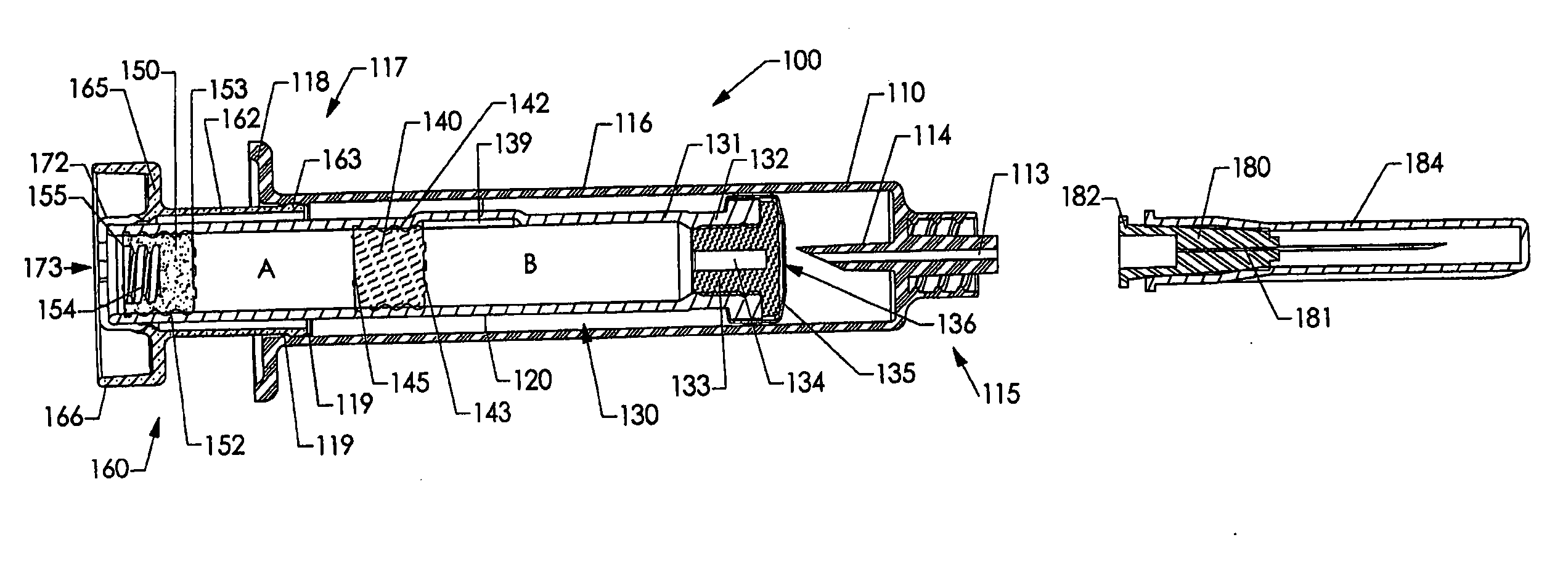
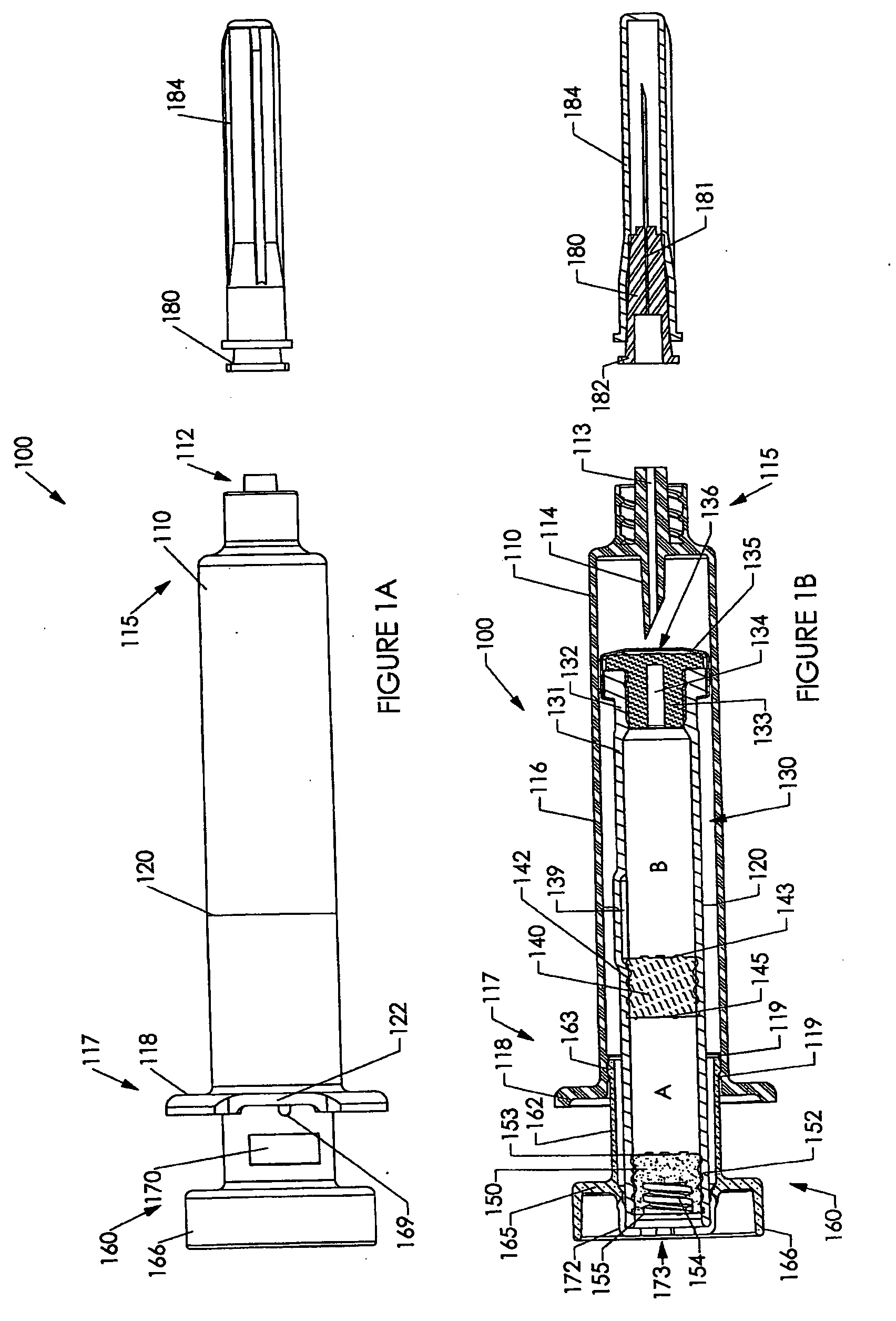
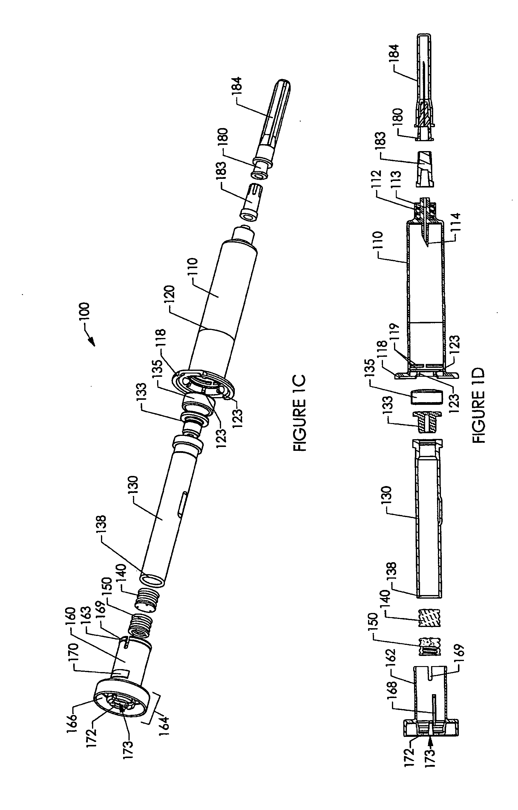
[0237] Various embodiments of the invention are shown in the drawings. Generally, like reference numerals are used, as between the drawings, to indicate like or similar features or functions. Further, where a particular feature or part is introduced in a drawing, the reference numeral for that feature or part begins with the figure number in the hundreds column. For example, for a feature introduced in FIG. 19, the reference numeral will be in the 1900s.

[0238] Where possible, reference numerals having the same number between 0 and 99, but having different increments of 100, are used to indicate like features or functions as between different embodiments shown in the drawings. For example, a syringe socket 110 is shown in FIGS. 1A to 1E, while an alternative syringe socket 1510 of another embodiment is shown in FIGS. 15A to 15D.

[0239] Throughout this specification, the term “distal” will be used to indicate a position, location or direction generally away from a person's hand while...


PUM

PropertyMeasurementUnit
taper angleaaaaaaaaaa
widthaaaaaaaaaa

Abstract

Embodiments of the invention relate generally to cartridges, devices and methods for pharmaceutical constituents for storage, mixing and delivery. Particular embodiments relate to a device and method for pharmaceutical constituent mixing and delivery using a double-chambered cartridge within a socket member, for use as part of a syringe device. Other embodiments relate to a cartridge assembly for storing the pharmaceutical constituents prior to mixing and a method of forming the cartridge assembly. Still further embodiments relate to an extensible plunger for actuation of the delivery device. The extensible plunger is actuated in a first stroke while in its retracted state to mix the constituents and is actuated in a second stroke in its extended state to deliver the mixed constituents to an external volume.

Description

CROSS REFERENCE TO RELATED APPLICATIONS [0001] This application claims the benefit of U.S. Provisional Patent Application Ser. No. 60 / 632,530, filed Dec. 3, 2004 and U.S. Provisional Patent Application 60 / 645,531, filed Jan. 21, 2005, the entire contents of both of which are hereby incorporated by reference.FIELD OF THE INVENTION [0002] The present invention relates generally to cartridges, devices and methods for pharmaceutical constituent storage, mixing and delivery. In particular aspects, the invention relates to a device and method for pharmaceutical constituent mixing and delivery using a double-chambered syringe. In other aspects, the invention relates to a cartridge assembly for storing the pharmaceutical constituents prior to mixing and a method of forming the cartridge assembly. BACKGROUND OF THE INVENTION [0003] In pharmaceutical delivery systems, it is sometimes necessary to mix a drug in powder form with a diluent in order to be able to deliver the drug to a subject. Th...

Claims


Application Information

Patent Timeline
Patent Type & Authority Applications(United States)
IPC IPC(8): A61M5/315
CPCA61J1/2093B65B3/003A61J2001/201A61J2001/2013A61M5/2448A61M5/2455A61M5/2466A61M5/31511A61M5/31515A61M5/3202A61M5/347A61M5/502A61M5/5066A61M2005/31508A61M2005/31518A61J1/2096A61J1/201A61J1/2013B01L2400/0478B01L2300/046B01L2300/0867B01L3/502B01L2200/16B01L2300/0832
Inventor REYNOLDS, DAVID L.
Owner DUOJECT MEDICAL SYSTEMS INC
Why Eureka
Try Eureka