Apparatus and method for wireless real time measurement and control of soil and turf conditions

a wireless real-time measurement and soil technology, applied in the field of apparatus and methods for wireless real-time measurement and control of soil and turf conditions, can solve the problems of wide-spread use of underground sensors, inability to accurately locate turf measurement sensors, and inability to meet the needs of real-time monitoring, etc., and achieve the effect of convenient calibration in pla

Inactive Publication Date: 2006-08-10
ADVANCED AERATION SYST
View PDF26 Cites 63 Cited by
  • Summary
  • Abstract
  • Description
  • Claims
  • Application Information

AI Technical Summary

Benefits of technology

[0006] The present invention provides a plurality of sensors connected to a radio to create a sensor node, which is buried in the root zone of turf on a golf course or other location. Data on soil conditions (especially soil conditions related to turf health parameters) is wirelessly transmitted in real-time from the node to a transceiver that is connected by a wireless or other network to a computer. The electronics for the sensor and the radio are integrated so the node is small enough to be placed in the root zone using a hole-cutting tool that is typically used to form a cup on a golf course green. Each node has one or more sensors with probes that measure a soil conditions. Sensor probes from a single node can be located at different soil depths. The sensors can be easily calibrated in place by sending calibration signals via the wireless radio link. Each node includes a power management algorithm so that the batteries that power the node will la...

Problems solved by technology

There are hand held instruments with probes that can be inserted in the soil to measure turf health but these are not practical for real time monitoring.
There are also applications of buried-in-ground sensors that measure turf health but these use underground wire to provide power and communications links to the above ground user and thi...

Method used


Image

  • Apparatus and method for wireless real time measurement and control of soil and turf conditions
  • Apparatus and method for wireless real time measurement and control of soil and turf conditions
  • Apparatus and method for wireless real time measurement and control of soil and turf conditions

Examples


Embodiment Construction

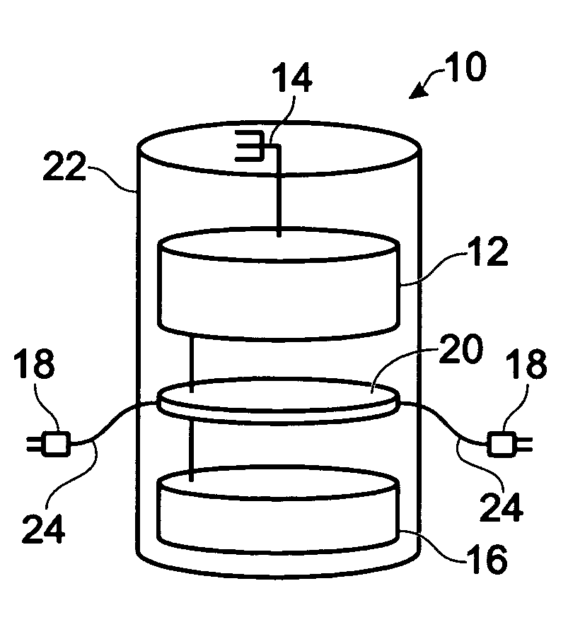
[0012] Referring now to the drawings, wherein like reference numerals refer to like parts throughout, there is seen in FIG. 1 a sensor node 10 according to the present invention, which comprises a radio 12, an antenna 14, a battery 16 (or other power supply), a number of sensors 18, and an electronic circuit board 20, all located in a node package 22. The node package 22 is slightly less than the diameter of a golf cup hole and less than 4 inches high. Preferably, the node package 22 consists of ABS plastic water pipe that has been sealed at each end with a standard pipe plug, but other packages 22 are also acceptable and will be known to those skilled in the art. Heavy duty waterproof wires 24 extend from the package 22 and are connected to sensors 18 that preferably include soil probes that extend radially into the soil at different depths so the probe is properly surrounded by soil and a good measurement is accomplished. The wires 24 protrude through one or more holes in the pack...


PUM


Abstract

An apparatus and method are provided for monitoring subsurface soil conditions in real time and communicating data about the subsurface soil conditions to a monitor that analyzes the data to provide warnings to the system operator and to automatically initiate one or more soil treatment processes. The apparatus includes nodes with soil condition sensors and radio transceivers. The nodes are communicatively connected by a network that includes at least one transceiver. The nodes optionally include means for controlling turf treatment devices in response to commands from the computer.

Description

[0001] This application claims priority to U.S. Provisional Patent Application No. 60 / 651,768, filed Feb. 9, 2005.FIELD OF THE INVENTION [0002] The present invention relates to an apparatus and method that uses subsurface sensors, a radio-linked network, and a computer for wireless, real-time monitoring, historical tracking and predictive modeling of subsurface soil conditions. The present invention also provides for automatic control of soil treatment equipment in response to data obtained by the sensors. BACKGROUND OF INVENTION [0003] Current turf management techniques use mainly local weather station information and soil appearance and feel to decide how to treat turf using irrigation, aeration, fumigation, fertilization, and other turf treatments. There are hand held instruments with probes that can be inserted in the soil to measure turf health but these are not practical for real time monitoring. There are also applications of buried-in-ground sensors that measure turf health ...

Claims


Application Information

Patent Timeline
IPC IPC(8): G01R21/00
CPCA01G1/002A01G25/167A01G20/00
Inventor GLANCY, JOHN E.MCINTOSH, DAVIDNORLEY, WALTER N.
Owner ADVANCED AERATION SYST
Why Eureka
Try Eureka