
Ion mobility spectrometer with parallel running drift gas and ion carrier gas flows

a technology of ion carrier gas and motion spectrometer, which is applied in the field of parallel running drift gas and ion carrier gas flow of motion spectrometer, can solve the problems of high cost of system preparation, low deflecting voltage, and difficulty in miniaturization, and achieves low cost of preparing a pattern database, uniform formation of electric deflecting field, and low cost

Inactive Publication Date: 2006-08-24
DRAGER SAFETY
View PDF14 Cites 4 Cited by
  • Summary
  • Abstract
  • Description
  • Claims
  • Application Information

AI Technical Summary

Benefits of technology

[0038] Another advantage of the present invention lies in the possibility of spectral analysis by means of varying the deflecting voltage. Compared to usual methods of pattern recognition, the expense for preparing a pattern database is omitted. For carrying out a spectral analysis, it is advantageous if a circuit is present that creates a potential distribution, in which the difference in potential between the counterelectrode and at least the detector electrode varies. A complete spectrum is obtained if the difference in potential is constantly varied. Furthermore, sections from an ion spectrum can be advantageously obtained if a potential distribution is created, in which the difference in potential between the counterelectrode and at least the detector electrode jumps among a plurality of fixed values. This embodiment is especially advantageous if the presence of selected substances shall be monitored.
[0039] For a detector electrode acting selectively depending on the established potential, it is advantageous if at least one auxiliary electrode is located in front of the detector electrode, viewed in the direction of flow. An especially uniform formation of the electric deflecting field can be obtained if at least one auxiliary electrode is additionally located behind the detector electrode, viewed in the direction of flow.
[0040] Work can be performed with especially low deflecting voltages if the electrodes are arranged, such that the electric field is formed at right angles to the direction of flow. For the implementation of the principle according to the present invention, it is basically sufficient if the detector electrode consists of a single electrode. However, it is especially advantageous if the detector electrode consists of a plurality of individually wirable sectors. In this way individual sectors can be assigned to the detector electrode or to an auxiliary electrode in terms of circuit wiring. As a result, the area of the detector electrode can be varied, and the resolution, on the one hand, and the sensitivity, on the other hand, of the IMS can be influenced depending on the requirements.
[0041] It is advantageous for optimal field geometry if all electrodes are arranged in parallel to one another, especially if the detector electrode and the auxiliary electrodes lie in one plane. For field geometry, it is likewise advantageous if the counterelectrodes are arranged in one area, the detector electrode and the auxiliary electrodes are arranged in another area, and the areas of the areas have about the same size, whereby structural shapes are to be preferred, in which these areas face each other congruently.
[0042] Especially good, reproducible results are obtained if the electrodes are made of platinum or gold.
[0043] For a good separation efficiency of the IMS according to the present invention, it is advantageous if the detector electrode is more narrow perpendicular to the direction of the flow than the cross-sectional area in the transition area that is mainly passed through by ion carrier gas. In this way, falsifications of the spectrum by ions from areas near the edge areas are prevented.

Problems solved by technology

The necessary high voltage is usually 2,000-3,000 V. Such systems are very expensive, complicated to manufacture and are miniaturized only with difficulty.
On the other hand, making a distinction between individual types of ions is not possible.
The separation efficiency of systems of this type is relatively poor, which may relatively frequently lead to the triggering of a false alarm.
Connected to this is the drawback that the measuring system must first learn the respective pattern, thus an extremely high calibrating expense is necessary.
Not considered mixtures, i.e., for example, combinations of analytes to be monitored with unknown impurities, may lead to false alarms or may prevent the detection of the analytes to be monitored.
Systems of this type are, however, expensive and extremely susceptible to environmental influences, such as pressure and humidity.

Method used


Image

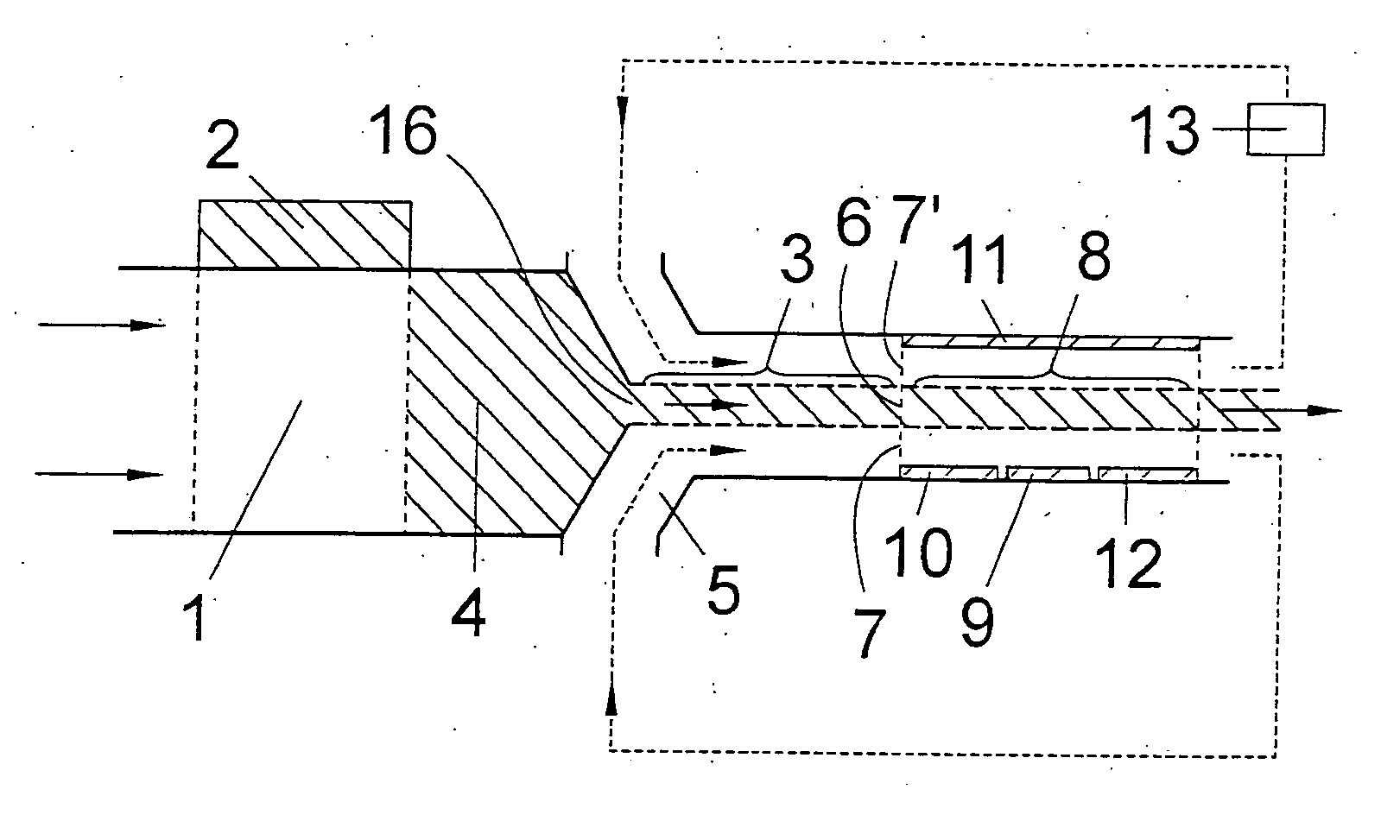
  • Ion mobility spectrometer with parallel running drift gas and ion carrier gas flows
  • Ion mobility spectrometer with parallel running drift gas and ion carrier gas flows
  • Ion mobility spectrometer with parallel running drift gas and ion carrier gas flows

Examples


Embodiment Construction

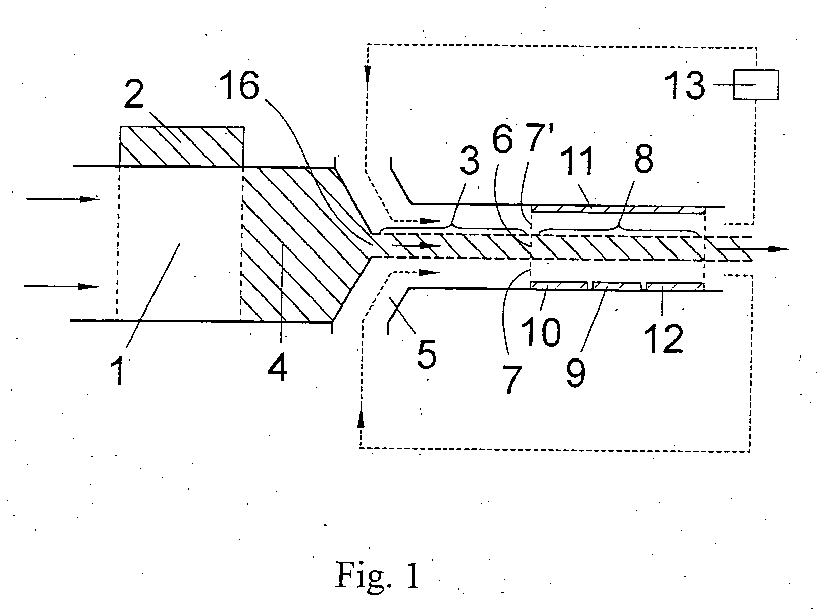
[0051] Referring to the drawings in particular, FIG. 1 shows a schematic view of an ion mobility spectrometer according to the present invention that requires only a relatively low voltage, which lies on the order of magnitude of below 50 V, for the separation of ions and therefore can be produced in a cost-favorable manner. Arrows illustrate the occurring gas flows.

[0052] The IMS comprises an ionization chamber 1, a radiation source 2 (shown as a cross hatched region) which emits beta radiation, and a transition area 3. Under the influence of the beta radiation, analyte-containing gas flowing through the ionization chamber is ionized. As a result, in terms of the present invention, ion carrier gas 4 (shown as a cross hatched region) is formed which flows into the transition area 3. Furthermore, an almost ion-free drift gas 5 is charged into the transition area 3. The ion carrier gas 4 (shown as a cross hatched region) and drift gas 5 are charged into the transition area 3 in a way...


PUM


Abstract

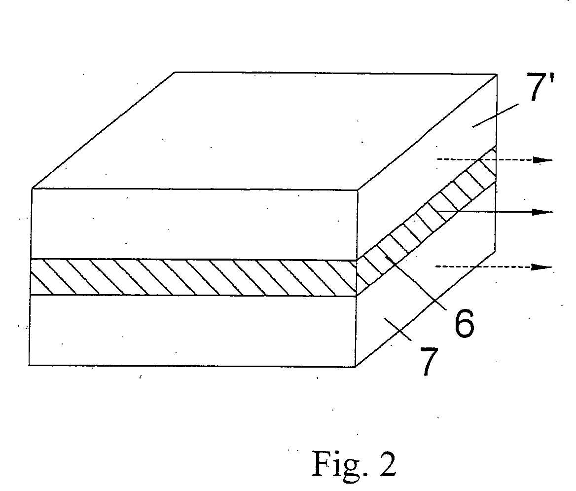
An ion mobility spectrometer is provided including at least one ionization chamber (1), which can be passed through by analyte-containing gas and at least one radiation source (2), from which ionizing radiation which is suitable for at least partially ionizing the analyte-containing gas enters the ionization chamber (1). At least one transition area (3) is provided, into which the at least partially ionized gas as ion carrier gas (4) and an almost ion-free gas as drift gas (5) can be charged in a way that, at least at the end of the transition area (3), a flow is established, in which cross-sectional areas (6) are mainly passed through by ion carrier gas (4) and other cross-sectional areas (7, 7′) are mainly passed through by drift gas (5). At least one separation area (8) is provided lying in the direction of flow behind the transition area (3), in which, likewise, cross-sectional areas are mainly passed through by ion carrier gas (4) and other cross-sectional areas are mainly passed through by drift gas (5). The drift gas (5) and ion carrier gas (4) flow unidirectionally, and the cross-sectional areas (6) that are mainly passed through by ion carrier gas (4) are smaller at least in one dimension than the cross-sectional areas (7, 7′) that are mainly passed through by drift gas (5).

Description

CROSS REFERENCE TO RELATED APPLICATIONS [0001] This application claims the benefit of priority under 35 U.S.C. § 119 of German Patent Application DE 10 2005 007 746.3 filed Feb. 18, 2005, the entire contents of which are incorporated herein by reference. FIELD OF THE INVENTION [0002] The present invention pertains to an ion mobility spectrometer with parallel running drift gas and ion carrier gas flows. BACKGROUND OF THE INVENTION [0003] Ion mobility spectrometers (IMS) are used for detecting trace substances in the air. They are widely used particularly in the detection of explosives, illegal drugs, chemical weapons and toxic industrial gases. The characteristic structural components of an ion mobility spectrometer are ionization chambers, drift chambers and detectors. The ionization chamber and the drift chamber in conventional ion mobility spectrometers are usually separated by a grid. In the ionization chamber, the analyte molecules to be determined are converted into ions. The ...

Claims


Application Information

Patent Timeline
IPC IPC(8): H01J49/40
CPCG01N27/622
Inventor ZIMMERMANN, STEFANBATHER, WOLFGANG
Owner DRAGER SAFETY
Learn More