However, efficiency is inherently limited by resistive losses and is particularly low at ordinary output levels, where only a fraction of the
power supply voltage is passed to the load.
Efficiency can be significantly improved by using intermediate-rail voltages with steering circuitry to reduce the average
voltage drop across the power transistors, but it adds complexity and introduces new sources of audio
distortion.
As a result, it becomes impractical to
mount a very
high power amplifier on or within a speaker because the
heat sink will be too large and fan cooling is undesirable due to the
noise and dust buildup.
The existing Class-D art suffers from: a) Poor
Linearity b) Poor Power Supply Rejection c) Poor
Frequency Response d) ON-OFF Noises Caused by Uncontrolled Onset of Switching Activity e) Overload and Overheating f) Excessive Switching Losses g) Excessive Switching
Noise h) Excessive Complexity and Cost
The causes of these deficiencies are briefly discussed: (a) Because the
transfer function is not uniform over the entire range of modulation, various errors occur after the modulator which result in
harmonic distortion (THD) of 1% or more, while high quality amplifiers need less than 0.1% THD.
Different speakers, loadings, and other conditions make this loading highly variable, causing unpredictable high-
frequency response.
(d) If switching is not started and stopped in a particular manner, transients are generated, causing “pops” in the speaker.
(e) Although theoretically lossless, actual Class-D schemes suffer from finite switching times and resistive losses, thereby generating a certain amount of heat.
These losses can be minimized with a slight “
dead time” between positive and negative switching transitions, but such
dead time is another source of poor
linearity.
The losses also depend on the magnitude of current flow, which must therefore be limited to some safe level.
Known
current limiting schemes are complicated by properties of typical switching devices (FETs) whose losses increase with rising temperature.
Setting protection limits that are safe at maximum temperatures may unduly limit performance at normal operating temperatures.
Furthermore, external current-monitoring schemes may fail to detect excessive currents due to abnormal internal conditions.
(f) Since switching losses are proportional to
switching frequency, it is desirable to switch at the lowest possible frequency, but audio performance will suffer due to complications in applying overall
negative feedback.
In general, switching systems are complex, with multiple
signal conversions, special
signal processing, and subsystems for driving the FET gates and maintaining orderly operation.
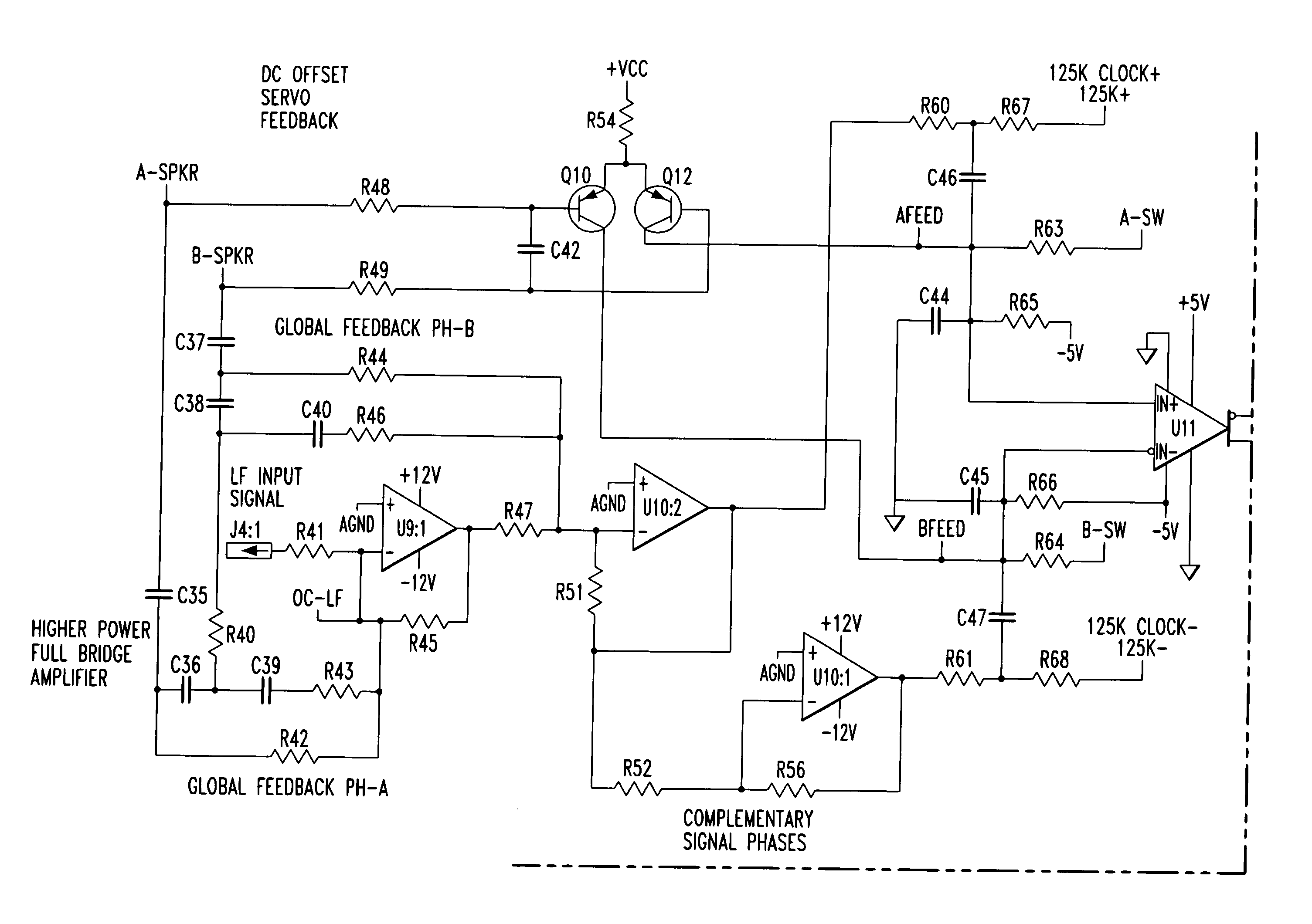
Global feedback around the entire
amplifier is often employed, to some effect, but the phase shift of the output filter, and the tendency to couple switching
noise back into the signal path, limits the amount of feedback that can be applied.
Furthermore, in a full-bridge topology, which is often desired for various practical reasons, there is no ground-referenced output terminal where a sense
resistor can conveniently be located.
Also, FET-type switching transistors have an on-resistance that increases with temperature and causes higher losses as temperature increases, leading to a potential “runaway” condition.
Additionally, external current monitoring schemes suffer from the phase shift of the output filter, thereby increasing the difficulty of
coupling overcurrent feedback signals back into the amplifier without oscillations.
Prior art either uses a single amplifier with a passive frequency-dividing network, which sacrifices performance and headroom, or dual amplifiers of similar construction, which fails to optimize their power for each speaker and frequency range.
Prior schemes whose
switching frequency diminishes near full modulation will emit more switching interference at full output, which interferes with orderly feedback.
Such schemes are often limited to less than full modulation, sacrificing potential output power.
This practice also significantly degrades efficiency at very high powers.
Overall
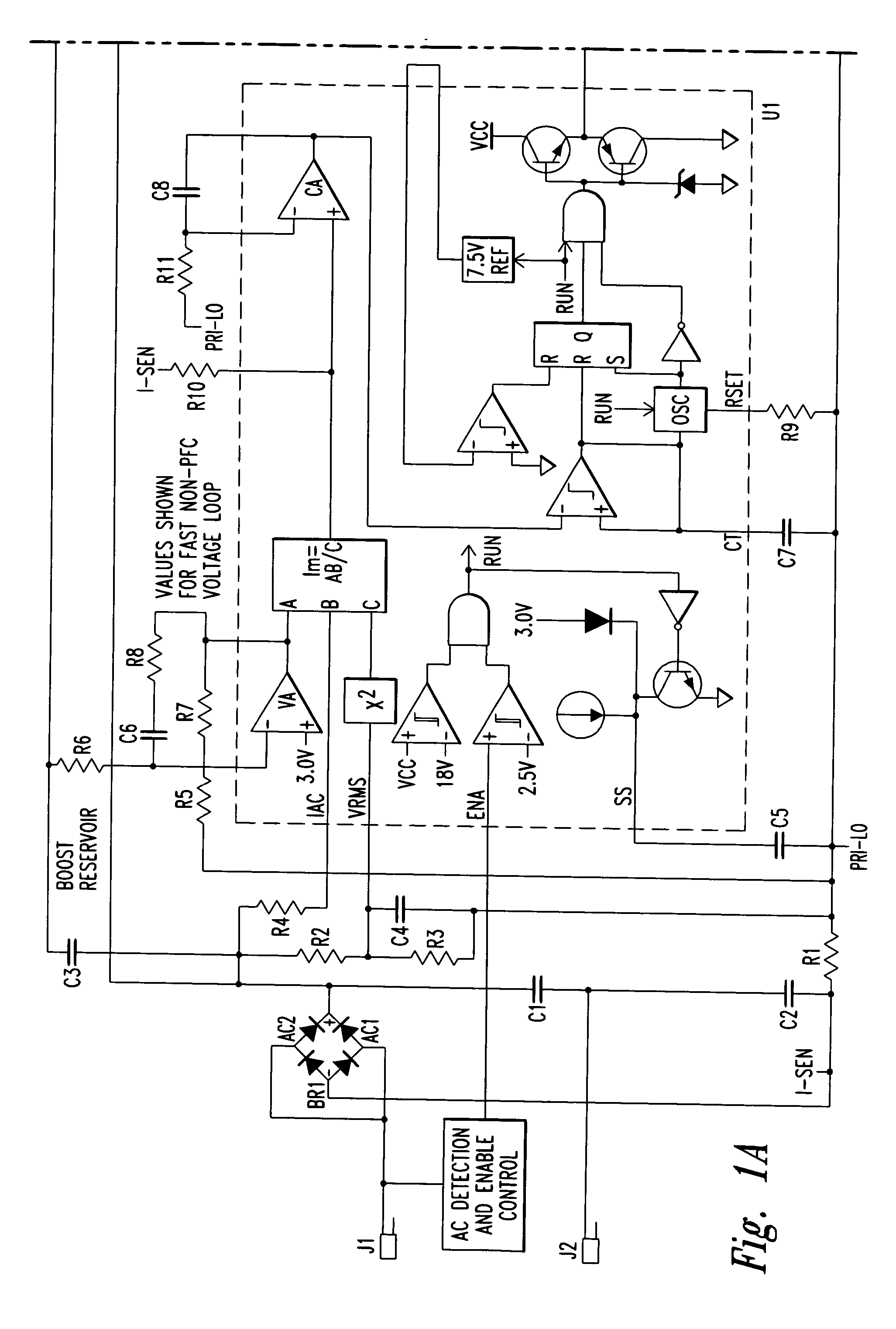
voltage feedback is usually taken from the main secondary; but when unloaded, many conventional
converters will reduce their switching activity to zero, thereby failing to support an auxiliary supply.
Furthermore, schemes for
coupling the regulating signal from secondary to primary side must meet strict isolation requirements and present a potential failure point that can result in complete loss of power supply control.
High frequency switching transitions can generate significant radio-frequency interference.
Such “EMI” is limited by regulations.
However, the primary-side power supply switches are necessarily somewhat coupled to the AC line, and their switching interference can be difficult to contain.

