[0014] By providing a line restrictor according to the invention, it is not necessary to perform any milling action along this line for establishing a linear groove, which facilitates the production process tremendously as compared to known processes. An optical disc with detachable module is in this way according to the invention produced in one step with a precise shaping during the moulding process.
[0020] The line restrictor inside the mould reduces the speed at which the
polymer may flow across the line restrictor. Because the distance between the edge of the restrictor and the opposite internal side of the mould is only spaced a
short distance, the
polymer is prevented from flowing across the line restrictor as freely as in the rest of the mould cavity. Therefore, temperature differences may occur across the hardening optical disc with detachable module which again may result in strain inside the hardened optical disc. This may have the consequence that the optical disc with the detachable module bends, when removed from the mould resulting in a non-satisfactory product.
[0021] In order to minimize such temperature differences when the
polymer is injected into the mould and flowing inside the mould to fill the cavity completely, the invention has foreseen a further development, where the line restrictor is comprised by a movable
plunger in order to establish the breaking line. Such a
plunger is preferably moved in a direction approximately orthogonal to the optical disc into the mould cavity. This action is performed after having supplied polymer into the cavity and before this polymer hardens. As the line restrictor is not inside the cavity during the filling of polymer into the mould, the polymer can flow freely inside the remaining cavity such that temperature differences across the polymer in the cavity is avoided. Still being a fluid, the
plunger in the form of a line restrictor is inserted and forms the groove for the breaking line between the detachable module and the optical disc. Though only one line restrictor and one plunger is mentioned in the foregoing and the following, this has to be understood also such that more than one line restrictor and plunger may be provided and used.
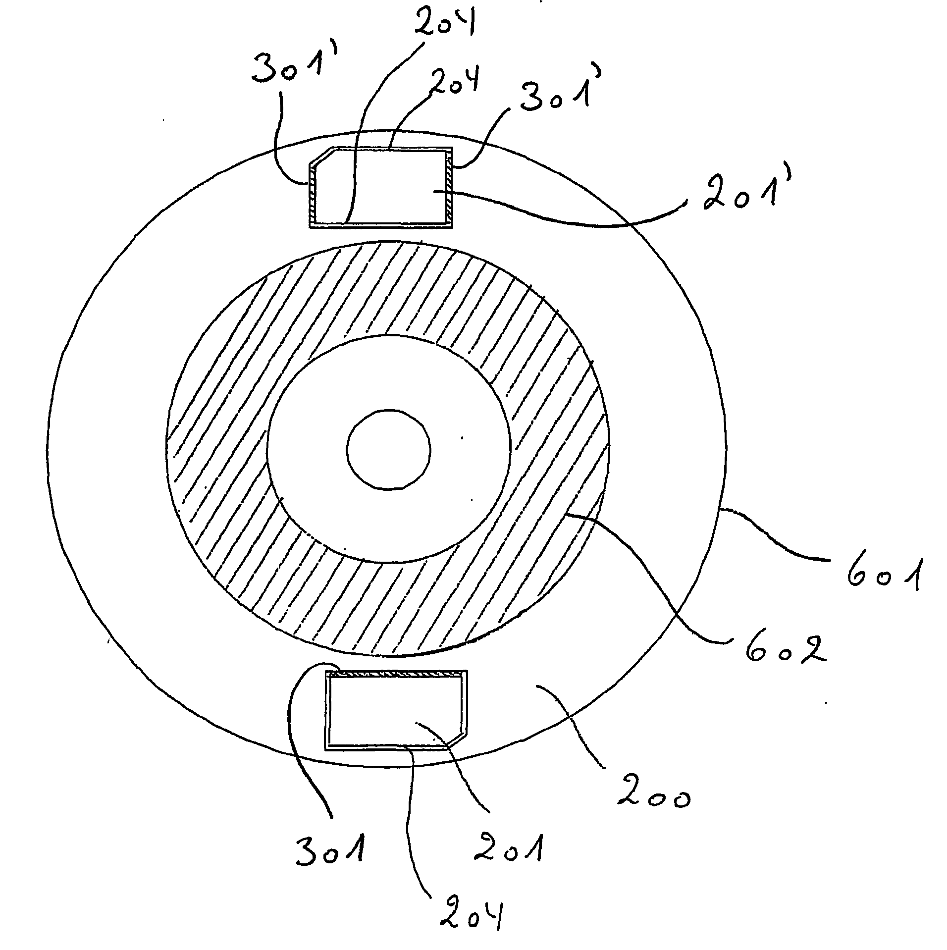
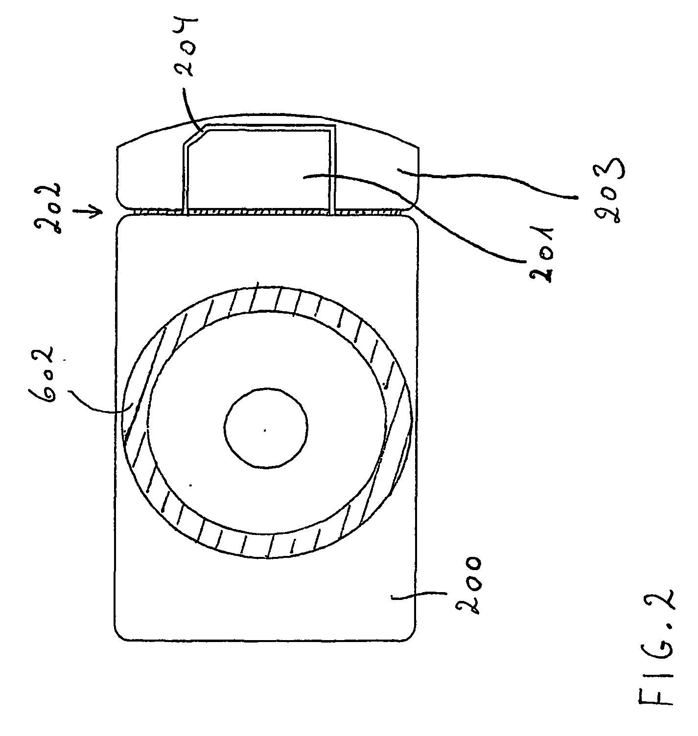
[0022] The detachable module that may be used for a SIM plug as mentioned earlier which has to be provided with a hollow for
insertion of an
electronic circuit. Also such a hollow can be produced by a plunger that is inserted into the cavity. Typically, a SIM plug has one hollow for the
electronic circuit and inside this hollow a second, deeper hollow for attaching the
electronic circuit to the SIM plate. This means that the material thickness of the polymer of the SIM plug at the thinnest is 0.2 mm. This implies in practice, if the mould form is
solid without a plunger, that polymer has to flow between two faces of 0.2 mm distance. In such a narrow region, the polymer may cool faster than in the rest of the cavity, which may induce stress in the optical disc with a detachable module as describe earlier. By using a plunger to form this deep second hollow in the SIM plug such a too-fast-cooling is avoided.
[0026] For a disc with detachable module according to the invention, such a
spinning method is not optimal, because the
coating may accumulate in the groove for the breaking line. Therefore, in a further development of the invention, it is foreseen that the
surface coating is applied by spraying or by silk
screen printing. It has turned out that spray-
coating has another
advantage as compared to spun
coating as will be apparent in the following. A spun coating has typically a
layer thickness 50 μm. Because a SIM plug has a very well-defined thickness, a 50 μm spun coating on the surface would imply that the polymer thickness between the glue in the hollow of the electronic module and the spun coating is only 0.15 mm, which is very thin and which easily may lead to deformation of the SIM plug during moulding and also during hardening of the spun coating and the applied glue inside the hollow. By applying
spray coating, the coating on the SIM plug can be made thinner or be completely avoided, such that the wall thickness is not 0.15 mm but 0.2 mm, which results in a higher stability against bending of this
thin wall.
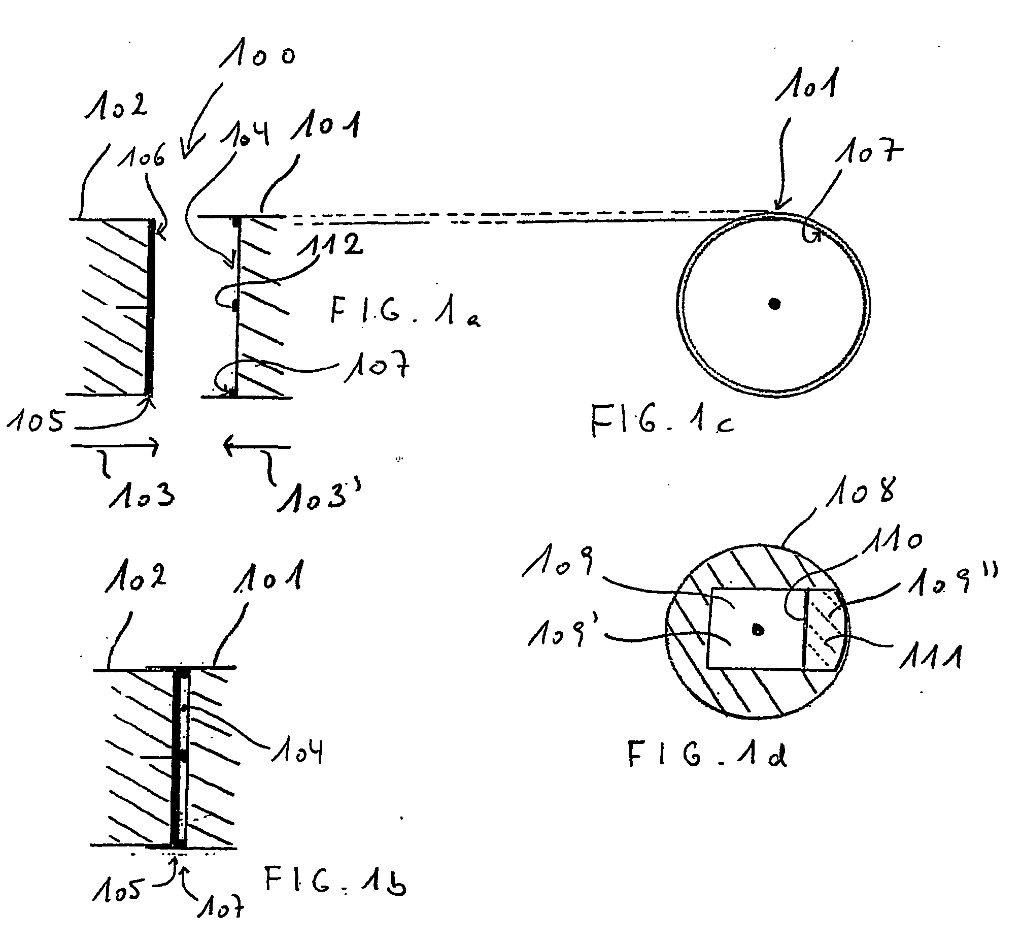
[0036] In case that the line restrictor is not comprised by a plunger and the line restrictor instead is a non-movable feature of the mould form or of the insert in the mould form, the line restrictor should be blunt for another reason. In case that the taper angles towards the module and facing away from the module are small, the line restrictor will be sharp and thin as a knife edge. This again implies that the
thin line restrictor may more easily be deformed when polymer under
high pressure is passing the narrow passage between the line restrictor and the opposite side of the mould. Partly, this can be prevented by using very hard materials, as for instance
tungsten carbide, however, steel may be desired as a material for the line restrictor by other reasons. Generally, the shape of the line restrictor may be designed in dependence of the
viscosity of the polymer and the distance between the line restrictor and the opposite side of the mould cavity.

