Surface treatment apparatus

a surface treatment and apparatus technology, applied in the field of surface treatment apparatus, can solve the problems of reducing the number of charged particles that collide with the substrate, and and achieve the effect of reducing the damage due to collisions of charged particles

Inactive Publication Date: 2006-08-31
MIZUKAMI HIROYUKI +3
View PDF5 Cites 182 Cited by
  • Summary
  • Abstract
  • Description
  • Claims
  • Application Information

AI Technical Summary

Benefits of technology

[0024] Further, it is possible to give electric potential to the substrate. In that case, it is possible to control energy of the charged particles, which have g

Problems solved by technology

Therefore, the number of the charged particles to collide with the subst

Method used


Image

  • Surface treatment apparatus
  • Surface treatment apparatus
  • Surface treatment apparatus

Examples


first embodiment

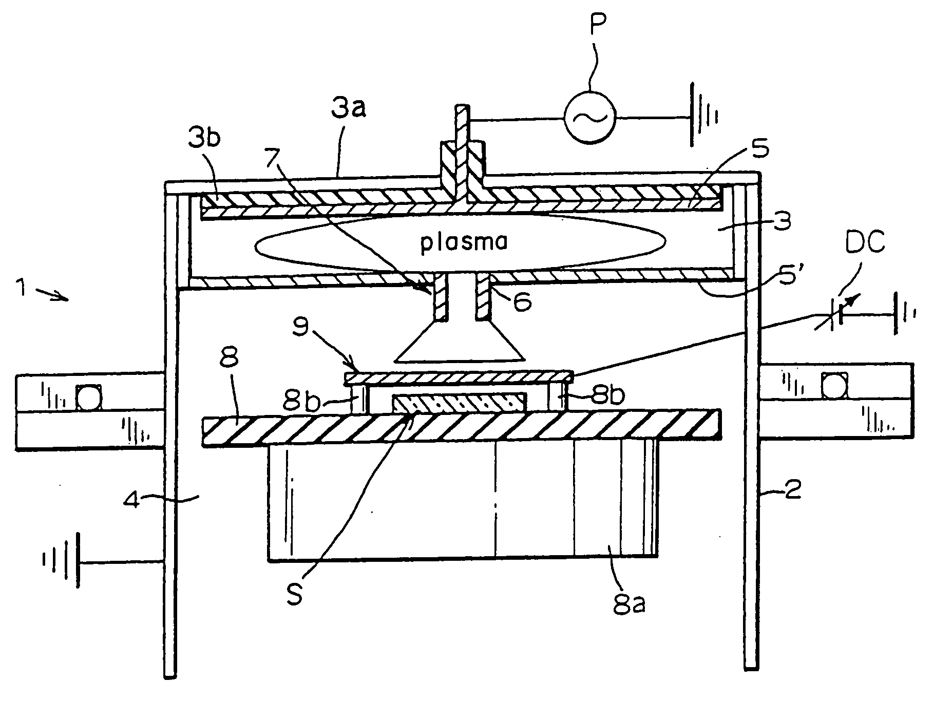
[0046]FIG. 1 is a schematic view of a surface treatment apparatus 1 according to the present invention. In the surface treatment apparatus 1, a grounded casing 2, which intercepts the air from outside, is partitioned to two chambers, that is, a plasma generating chamber 3 and a substrate processing chamber 4. The plasma chamber 3 is provided with a raw-gas inlet (not shown) for introducing raw gas such as monosilane gas or the like. Furthermore, from the raw-gas inlet, carrier gas, which is mixed with the raw gas, is introduced in order to enhance the generation of the plasma, stabilize the plasma and carry the raw gas to a substrate S. An inlet dedicated for the carrier gas may be provided.

[0047] Further, a pair of plate-like plasma generating electrodes 5, 5′, which are connected to a high-frequency electric power supply P, are disposed in the plasma generating chamber 3. One electrode 5 of the paired two electrodes 5, 5′ is attached to an upper wall 3a of the plasma generating ch...

second embodiment

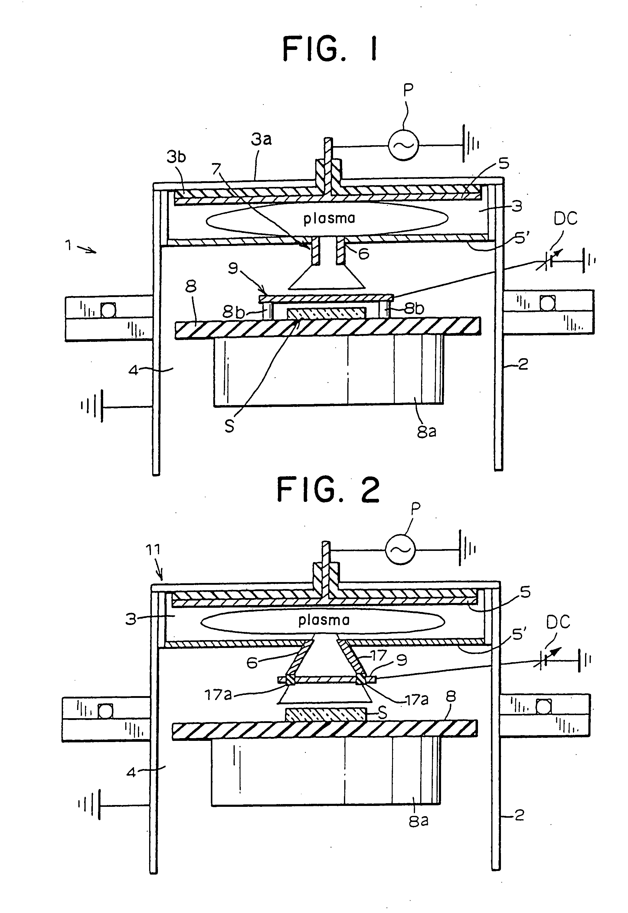
[0056] According to the surface treatment apparatus 11 of the second embodiment, a nozzle body 17, which is attached to a plasma vent 6, has a circular section and has such a truncated cone shape whose diameter extends from a plasma generating chamber 3 toward a substrate processing chamber 4. The mesh-shaped conductive sheet 9, which is connected to a direct current power supply DC, is attached via an insulating material 17a at an end face of the nozzle body 17 on a side toward the substrate processing chamber 4.

[0057] Similarly to the above described first embodiment, the surface treatment apparatus 11 of the second embodiment is also provided with a mesh conductive sheet 9 which is disposed orthogonal to the plasma flow. By applying a negative bias to a variable power supply of this conductive sheet 9, it is possible that the plus charged particles are captured by the sheet 9. Alternatively, by applying a positive bias to the sheet 9, it is possible that the plus charged particle...

fourth embodiment

[0061]FIG. 5 is a schematic view of a surface treatment apparatus 31 according to the present invention. In the surface treatment apparatus 31, a mesh-shaped conductive sheet 9 is attached in the vicinity of a plasma vent 6 on a side toward a plasma generating chamber 3 so as to cover the vent 6, while an insulating material 5a′ is disposed between the conductive sheet and an electrode 5′. In other words, the conductive sheet 9 is disposed so as to be orthogonal to the plasma, which flows out from the plasma vent 6, so that all the plasma, which flow out from the plasma generating chamber 3 to the substrate processing chamber 4, passes through the conductive sheet 9. As a result, the charged particles are excluded.


PUM

PropertyMeasurementUnit
Speedaaaaaaaaaa
Shapeaaaaaaaaaa
Electrical conductoraaaaaaaaaa

Abstract

The present invention has an object to provide a surface treatment apparatus, which can form a high-quality film at a high speed while preventing deterioration of the film due to collisions of charged particles.
The surface treatment apparatus (1) of the present invention comprises a casing (2) partitioned to two chambers, that is, a plasma generating chamber (3) provided with plasma generating electrodes (5, 5′) and a substrate processing chamber (4) provided with a substrate supporting table (8). A plasma vent (6) is formed in the electrode (5′) that composes the partition between the chambers (3, 4). A conductive mesh-shaped sheet (9) is disposed in a direction across the plasma between the plasma vent (6) and a substrate (S) on the substrate supporting table (8). The sheet (9), to which a variable bias is applied, captures charged particles in the plasma so that the charged particles can be excluded from the plasma.

Description

FIELD OF THE INVENTION [0001] The present invention relates to a surface treatment apparatus, which suits various surface treatments for a substrate, especially a film formation processing for a substrate. More specifically, it relates to a surface treatment apparatus that can reduce the damage occurred by charged particles existing in plasma flow and is capable of forming a high-quality film at a high speed. RELATED ART [0002] In a conventional parallel and tabular plasma CVD (Chemical Vapor Deposition) apparatus, a pair of tabular plasma generating electrodes are provided so as to be opposed in parallel to each other in a casing. Of these two plasma generating electrodes, one electrode also functions as a substrate supporting table. Further, this CVD apparatus is provided with a heater for adjusting temperature of the substrate to the temperature that is proper for vapor phase epitaxy. If voltage is applied between the two plasma generating electrodes by a high-frequency electric ...

Claims


Application Information

Patent Timeline
IPC IPC(8): C23C16/00C23C16/50H01J37/32H01L21/205H01L21/31
CPCA63B2243/0029C23C16/45563C23C16/45565C23C16/509H01J37/32357A63B2102/32
Inventor MIZUKAMI, HIROYUKITAKASHIRI, MASAYUKITOYOSHIMA, YASUMASATABUCHI, TOSHIHIRO
Owner MIZUKAMI HIROYUKI
Why Eureka
Try Eureka