Radiotherapy apparatus monitoring therapeutic field in real-time during treatment

a technology of radiotherapy apparatus and therapeutic field, which is applied in the field of radiotherapy apparatus, can solve the problems of inability to monitor the real-time radiation field, inability to achieve real-time follow-up irradiation to a therapeutic field which moves at a high speed due to heart pulse movement, and inability to achieve high-speed position control

Active Publication Date: 2006-08-31
HITACHI LTD
View PDF6 Cites 132 Cited by
  • Summary
  • Abstract
  • Description
  • Claims
  • Application Information

AI Technical Summary

Benefits of technology

[0014] Therefore, it is an object of the present invention to provide a radiotherapy apparatus that can monitor a therapeutic field state in real time even during radiation irradiating radiotherapy.

Problems solved by technology

In the lineac therapy apparatus, high-speed position control is not possible.
Consequently, real-time follow-up irradiation to a therapeutic field which moves at a high speed as movement due to heart pulses is not possible.
Because the therapeutic X-ray provides strong permeability and has many scattering radiations, the picture quality for real-time monitor of the radiation field is not superior.
In this method, it is not practiced to grasp the position of the actual diseased part in real-time and to irradiate radiation to it while tracking in such a manner that the actual position of the diseased part overlaps the radiation field.
In addition, there is a case that the image detector enters the shadow of a main body of the lineac therapy apparatus, so that the diagnostic X-ray from the X-ray generating unit may not reach the image detector.
In addition, due to the rotation of the lineac therapy apparatus, the image detector enters the shade of the apparatus and diagnostic X-rays from the X-ray generating unit may not reach the image detector.
However, the irradiation system is isocentric.
In addition, though breathing and heart pulses are cyclic movements, movements of organs associated with them do not always pass the same route every time.

Method used


Image

  • Radiotherapy apparatus monitoring therapeutic field in real-time during treatment
  • Radiotherapy apparatus monitoring therapeutic field in real-time during treatment
  • Radiotherapy apparatus monitoring therapeutic field in real-time during treatment

Examples


first embodiment

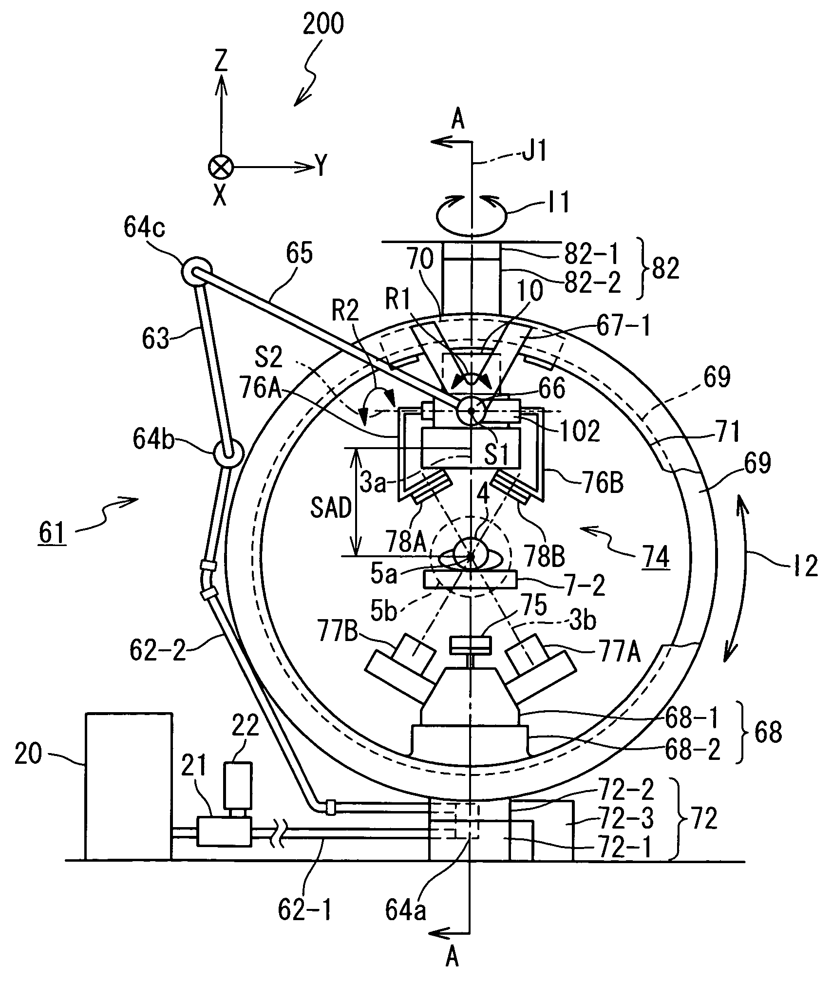
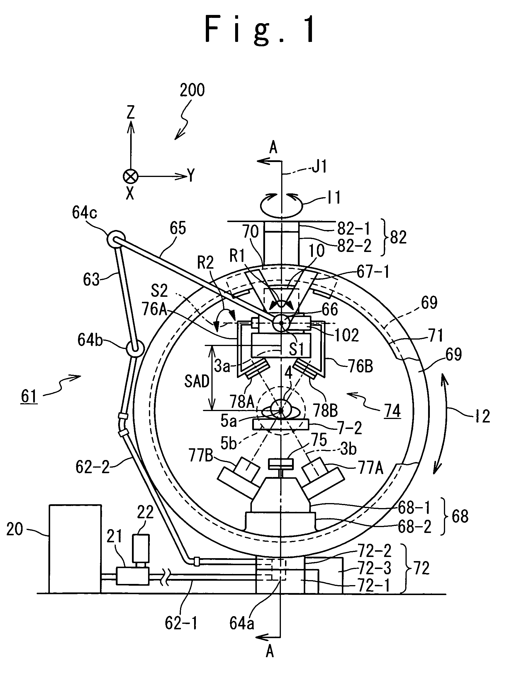
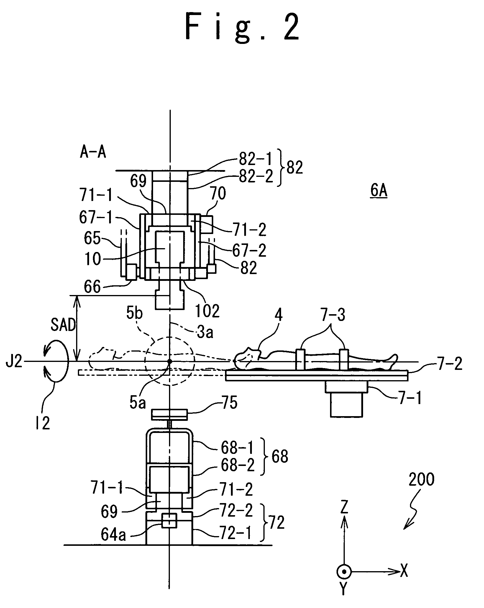
[0058] The radiotherapy apparatus according to the first embodiment of the present invention will be described. FIGS. 1 and 2 are a front view and a cross sectional side view showing the structure of the radiotherapy apparatus according to the first embodiment of the present invention. In the drawings, a part of the structure of the radiotherapy apparatus is omitted. Coordinate axes 200 indicate a three-dimensional orthogonal coordinate system which has X-axis, Y-axis, and Z-axis in FIG. 1 and FIG. 2.

[0059] The radiotherapy apparatus 6A includes a therapeutic bed system 7, an X-ray head 10, a support frame 67-1, a support frame 67-2, an O-type gantry 69, a movement following type waveguide tube system 61, a microwave generating unit 20, and a real-time imager 74.

[0060] The therapeutic bed system 7 includes a bed driving system 7-1, a therapeutic bed 7-2, and a patient fixing apparatus 7-3. The therapeutic bed 7-2 is loaded with a patient 4 who undergoes radiotherapy, and is moved ...

second embodiment

[0167] The radiotherapy apparatus according to the second embodiment of the present invention will be described in detail below with reference to the attached drawings. FIG. 18 and FIG. 19 are a front view and a side view showing the configuration of the radiotherapy apparatus according to the second embodiment of the present invention. For these diagrams, parts are partly omitted and indicated. Coordinate 200 shows the 3-dimensional orthogonal coordinates which have X-axis, Y-axis, and Z-axis in FIG. 18 and FIG. 19.

[0168] The radiotherapy apparatus 6B includes the therapeutic bed system 7, the X-ray head 10, the support frame 67-1, the support frame 67-2, the C-type gantry 89, the waveguide tube system 61, the microwave generating unit 20, and the real-time imager 30.

[0169] The C-type gantry 89 includes a head circumferential moving mechanism 33, the gantry rotating mechanism 72, and the upper support mechanism 82.

[0170] The C-type gantry 89 (main body) is installed as if it sur...

third embodiment

[0191] Referring now to the attached drawings, the radiotherapy apparatus according to the third embodiment of the present invention will be described in detail. FIG. 20 and FIG. 21 are a front view and a side view showing the configuration of the radiotherapy apparatus according to the third embodiment of the present invention. For the drawings, parts are partly omitted and indicated. The coordinate 200 shows the three-dimensional orthogonal coordinates in the X-axis, Y-axis, and Z-axis directions in FIG. 20 and FIG. 21.

[0192] The radiotherapy apparatus 6C includes the therapeutic bed system 7, the X-ray head 10, the support frame 102, the Ω-type gantry 9, the waveguide tube system 61, the microwave generating unit 20, the support bed 29, and the real-time imager 30.

[0193] The Q-type gantry 9 includes the gantry tilting mechanism 28, the head circumferential moving mechanism 33, and the wiring 32. The Ω-type gantry 9 is provided with a semicircular ring which forms an upper half ...


PUM


Abstract

A radiotherapy apparatus includes an irradiation head section, an X-ray source section and a sensor array section. The irradiation head section irradiates therapeutic radiation to a therapeutic field of a target substance. The X-ray source section irradiates diagnostic X-rays to the therapeutic field of the target subject. The sensor array section detects the diagnostic X-rays which have transmitted the target subject, and outputs diagnostic X-ray image data based on the detected diagnostic X-rays. The sensor array section moves in conjunction with movement of the irradiation head section.

Description

BACKGROUND OF THE INVENTION [0001] 1. Field of the Invention [0002] The present invention relates to a radiotherapy apparatus and more specifically to a radiotherapy apparatus used for stereotactic radiotherapy. [0003] 2. Description of the Related Art [0004] A radiotherapy apparatus for treating cancers and tumors using radiation is known. As a 3-dimensional irradiation radiotherapy apparatus which irradiates stereotactic multi-path radiotherapy apparatus, radio-surgery therapy apparatus, lineac (medical linear accelerator) therapy apparatus, and others are known in “Radiotherapy physics”, by Takehiro Nishidai, (Bunkodo, Feb. 26, 2001, pp. 95-153) and “Radiotherapy Manual”, by Masahiro Hiraoka, Keishi Sasai, and Toshihiko Inoue, (Chugai-Igakusha, Apr. 10, 2001, pp. 19-63). [0005] Now, stereotactic multi-path irradiation is radiotherapy to irradiate radiation concentratedly to a small seat of disease from multi-directions to achieve radiotherapy effects, and at the same time, to hol...

Claims


Application Information

Patent Timeline
Patent Type & Authority Applications(United States)
IPC IPC(8): A61N5/10
CPCA61N5/1049A61N5/1067A61N5/1082A61B6/4458A61B6/4464A61N2005/1061
Inventor HARA, KENJIAKATSU, MAKOTOKAWATA, NORIYUKI
Owner HITACHI LTD
Why Eureka
Try Eureka