Apparatuses and methods for deposition of material on surfaces

a technology of surface deposition and apparatus, applied in the direction of crystal growth process, chemically reactive gas, coating, etc., can solve the problems of non-uniform cvd (chemical vapor deposition) growth of film on the substrate, drastically shortening the life of the gate valve, and complex deposition cycl

Active Publication Date: 2006-09-07
PICOSUN OY
View PDF58 Cites 333 Cited by
  • Summary
  • Abstract
  • Description
  • Claims
  • Application Information

AI Technical Summary

Benefits of technology

[0018] It is an object of embodiments of the invention to provide a compact ALD reactor for R&D and production purposes with a reaction chamber and a substrate holder that can be accessed from the top side of the reaction chamber. A further object is to provide a modular ALD reactor that can be tailored for specific applications relating to the coating of single substrates, multiple substrates and solid particles. A still further object is to provide an ALD reactor that allows step-wise propagation from R&D stage to production stage without substantial structural alterations to the said ALD reactor.

Problems solved by technology

Deposition cycles can also be more complex.
Long flow path causes problems with processes where reaction by-products can re-adsorb on the substrate surface and block reactive surface sites.
One of the problems with the design is that pulsing valve attached directly to the lid are rather vulnerable to gas leaks, which may result in non-uniform CVD (Chemical Vapor Deposition) growth of film on the substrate.
A problem with the reactor is that the expensive gate valve is exposed to the process temperature, which may drastically shorten the lifetime of the gate valve.
A problem with the reactor is that the reaction by-products, such as hydrogen chloride HCl, can readsorb on the surfaces of the down stream side substrates causing non-uniform film growth.
A problem with the reactor is that when the reactor is pressurized to atmospheric pressure and the flange of the reactor tube is opened for accessing the coated particles, any solid precursor left within the source tube is exposed to room air because the source tube is in fluid communication with the reaction chamber.
One general problem is that, in most known reactors, the top part of the reactor must laboriously be disassembled before the reaction chamber can be serviced.
Also, the footprint of these reactors is rather large and they typically have high electrical power consumption.

Method used


Image

  • Apparatuses and methods for deposition of material on surfaces
  • Apparatuses and methods for deposition of material on surfaces
  • Apparatuses and methods for deposition of material on surfaces

Examples


example 1

Deposition of a Binary Thin Film on a Single Substrate

[0105] Trimethyl aluminum (CH3)3Al, referred to as TMA hereinafter, and water were used as precursors for the deposition of Al2O3 thin film on heated surfaces within the reaction space of the SUNALE™ R-150 ALD reactor manufactured by Picosun Oy, Finland. TMA is liquid at room temperature and it has a vapor pressure of 13 hPa at 22° C., wherein 1 hPa=100 Pa=1 mbar. TMA can be injected from a temperature-controlled high-pressure liquid source. The source temperature for TMA was 20° C. Water is liquid at room temperature and it has a vapor pressure of 23 hPa at 20° C., which means that it can also be injected from a temperature-controlled high pressure liquid source. The source temperature for H2O was 20° C.

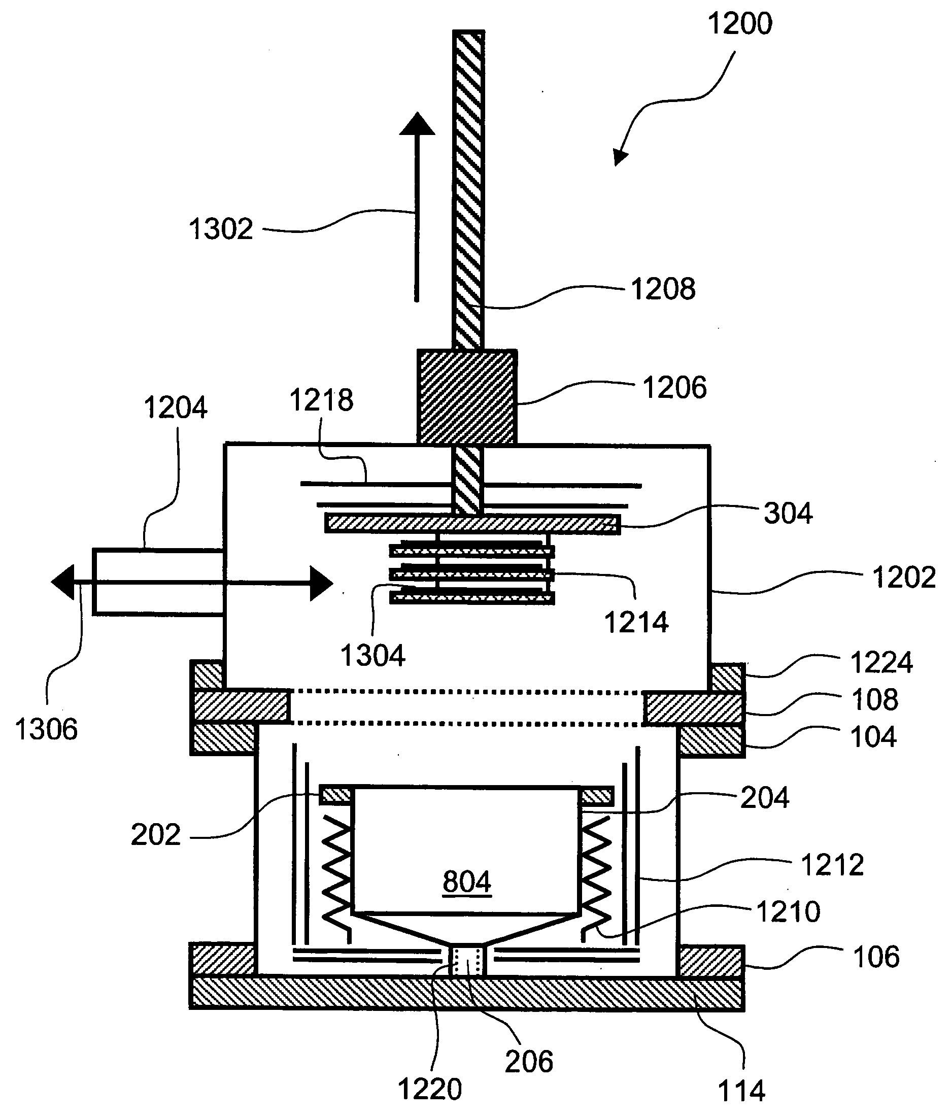
[0106] In this example a 150-mm silicon wafer with microelectromechanical structures (MEMS) on the wafer surface serves as a substrate. The dual-lid system was raised with a lifting mechanism to the upper position for accessing...

example 2

Deposition of a Ternary Metal Oxide on a Minibatch

[0109] Tetrakis(trimethylsiloxy)titanium [(CH3)3SiO]4Ti, referred to as TTMST hereinafter, was used as the titanium and silicon precursor. TTMST is liquid at room temperature and it has a vapor pressure of 13 hPa at 110° C., which means that it can be injected from a Heated Precursor Delivery System (HPDS). Water H2O and O3 were used as oxygen precursors. Water was injected from a temperature-controlled high pressure liquid source. Ozone is gas at room temperature and it was injected as ozone—oxygen gas mixture from a gas source.

[0110] The TTMST source was heated to a temperature selected from a temperature range of about 100-130° C. In this deposition example the TTMST source temperature was 120° C. The water source temperature was controlled with a peltier element cooler so that the temperature of the water source was preferably slightly below the room temperature, although temperatures above the room temperature can be used in o...

example 3

Deposition of a Multilayer Thin Film on Solid Particles

[0118] Rhenium is a very expensive element and it is advantageous to minimize the consumption of Re compounds in processes. On the other hand, the surface of the substrate is not always optimal for the growth of metals without a pretreatment. The flexibility of the present ALD reactor makes it possible to have an ALD reactor with four precursor sources, so that the pretreatment and the actual coating can be done with a single pump down in one reactor.

[0119] TMA was used as an aluminum precursor. TMA was injected from a temperature-controlled high-pressure liquid source. Water was used as the oxygen precursor and it was also injected from a temperature-controlled high-pressure liquid source. Rhenium trioxychloride ReO3Cl was used as the rhenium source chemical. ReO3Cl is liquid at room temperature and it has a vapour pressure of 1013 hPa at 131° C. It was injected from a heated high pressure liquid precursor source. A person sk...


PUM

PropertyMeasurementUnit
thicknessaaaaaaaaaa
widthaaaaaaaaaa
heightaaaaaaaaaa

Abstract

An apparatus for depositing conformal thin films by sequential self saturating chemical reactions on heated surfaces is disclosed. The apparatus comprises a movable single or dual-lid system that has a substrate holder attached to a reaction chamber lid. In other embodiments, the apparatus comprises an exhaust flow plug, a gas distribution insert, a local heater or a minibatch system. Various methods suitable for ALD (Atomic Layer Deposition) are also enclosed.

Description

FIELD OF THE INVENTION [0001] The present invention generally relates to the deposition of material on a surface. More particularly, but not exclusively, the invention relates to the deposition of material on heated surfaces by sequential self-saturating surface reactions below the atmospheric pressure, and to an apparatus and a method for growing conformal thin films. BACKGROUND OF THE INVENTION [0002] Atomic Layer Epitaxy (ALE) method was invented by Dr. Tuomo Suntola in the early 1970's. Another generic name for the method is Atomic Layer Deposition (ALD) and it is nowadays used instead of ALE. ALD is a special chemical deposition method based on the sequential introduction of at least two precursor species to a substrate that is located within a heated reaction space. The growth mechanism of ALD relies on the bond strength differences between chemical adsorption (chemisorption) and physical adsorption (physisorption). During chemisorption a strong chemical bond is formed between...

Claims


Application Information

Patent Timeline
Patent Type & Authority Applications(United States)
IPC IPC(8): C23C16/00
CPCC23C16/45525C23C16/45546C23C16/45578C23C16/4583C23C16/52C23C16/45587C23C16/458C30B25/02C30B25/12C30B25/14
Inventor LINDFORS, SVENPOUTIAINEN, JUHA ALLAN KUSTAA-ADOLF
Owner PICOSUN OY
Why Eureka
Try Eureka