Current control apparatus for electric load

a current control and electric load technology, applied in the direction of electric control, magnetic bodies, instruments, etc., can solve the problems of reducing the control load of the microprocessor, the inability to perform current interruption, and the complexity of the hardware configuration thereof, so as to improve the reduction of current detection accuracy, the effect of effective calibration elements and easy protection measures

Active Publication Date: 2006-09-07
MITSUBISHI ELECTRIC CORP
View PDF0 Cites 26 Cited by
  • Summary
  • Abstract
  • Description
  • Claims
  • Application Information

AI Technical Summary

Benefits of technology

[0030] Accordingly, one object of the present invention is to obtain a current control apparatus for an electric load in which a current detection resistor is connected between a switching element and an electric load so as to make easy protective measures against load short-circuit accidents, and which is capable of providing an effective calibration element to improve reduction in current detection accuracy.
[0031] Another object of the present invention is to provide a current control apparatus for an electric load which is constructed so as to be free from the influence of an overcurrent detection circuit used as a protective measure against load short-circuit accidents, thereby making it possible to prevent reduction in the digital conversion accuracy of an AD converter.
[0032] A further object of the present invention is to provide a current control apparatus for an electric load which is capable of improving accuracy in the detection and warning of an abnormal state such as a positive phase power supply fault accident in which a current detection resistor is short-circuited with external wiring.
[0034] According to the present invention, the switching element and the current detection resistor are connected with each other in a mutually adjacent relation, so special wiring to the electric load can be eliminated. Besides, in the apparatus of a feeder circuit construction in which a burnout preventive measure against a short-circuit malfunction of the wiring or the electric load is simplified by the current limiting function of the current detection resistor, it is possible to perform highly accurate current control by supplementing deterioration in current detection accuracy. Moreover, since detection errors are calibrated according to respective factors for the detection errors, it is possible to carry out highly accurate current control by utilizing calibration constants in an appropriate manner during the operation of the current control apparatus in various driving environments.

Problems solved by technology

In the apparatus of the external feedback control type described in the third patent document, the control load of the microprocessor is reduced, but the hardware configuration thereof becomes complicated.
As a result, a warning indication can be carried out upon detection of an abnormal state, but current interruption cannot be performed.
However, since an excessively large load current does not flow, the possibility of causing a burnout accident at once is small.
In this case, it is possible to detect abnormality because the detected current abnormally falls or decreases in spite of the fact that an energization command is provided to the switching element, but even if the switching element is interrupted or turned off quickly by the detection of abnormality, an abnormally excessive current flows through the switching element.
Thus, this is an abnormal mode of a high probability that there occurs an internal short circuit of the switching element itself, and hence the switching element might subsequently be burned out to be open circuited.
In this case, abnormality can be detected due to the fact that the detected current abnormally falls despite the fact that an energization command is provided to the switching element, so the switching element can be interrupted or turned off by the detection of abnormality.
Consequently, a warning indication can be carried out upon detection of an abnormal state, but current interruption cannot be performed, thus resulting in an abnormal mode in which a burnout accident of the current detection resistor or a break or disconnection accident thereof occurs.
In short, the feeder circuit described in the first or third patent document is constructed such that the switching element and the current detection resistor are connected at positions apart from each other with the electric load interposed therebetween, as a result of which there will be a very high probability that when a hetero-phase power supply fault accident or a hetero-phase ground fault accident occurs, protection of these parts is difficult, thus leading to burnout accidents thereof.
In this case, abnormality is detected by abnormal reduction of the detected current in spite of the fact that an energization command is provided to the switching element.
As a result, an abnormal state can be detected to make a warning indication but current interruption cannot be performed.
However, an excessively large load current does not flow, so the possibility of causing a burnout accident at once is small.
Accordingly, it is ideal from the viewpoint of overcurrent protection to directly connect the switching element and the current detection resistor with each other as in the case of the second patent document, but on the other hand, there exist, as will be described later, two problems; one is great reduction in current detection accuracy, and the other is that a negative voltage is impressed to a differential amplifier for current detection by a commutating diode connected in parallel to the electric load, thus causing a malfunction of the differential amplifier.
However, there exist an individual variation of the resistance value of the current detection resistor and an offset error of the amplifier or an AD converter when the current value is in the zero state.
Thus, in the case of the method of detecting an overcurrent by the output voltage of the current detection circuit, when the value of a current detection signal changes from 0 [V] to 5 [V] for instance, in order to prevent inadvertent abnormality detection at voltages in the vicinity of 5 [V], a normal signal voltage needs to be in a very low voltage range, and hence there arises a problem that digital conversion accuracy of the AD converter is reduced.
Here, note that the provision of overcurrent detection resistors, the differential amplifier, a comparison determination circuit, and a latch circuit, as shown in FIG. 6 in the second patent document, results in a costly construction which, in particular, requires two current detection resistors that are heat-generating parts, so such a construction is undesirable from the viewpoint of size reduction and power saving.
In the above-mentioned conventional current control apparatuses, for instance, the first or third patent document has a problem that it is difficult to take protective measures against hetero-phase power supply faults or hetero-phase ground faults of the electric load.
Also, in the second, fourth or fifth patent document, protection against short-circuit accidents becomes easy but there is a problem that current detection errors due to the energization duty of the switching element or variation of the power supply voltage have a great influence on current detection accuracy.
In addition, in the first or fourth patent document, calibration means for improving current detection accuracy is disclosed but has a problem that current detection errors caused by the energization duty of the switching element or variation of the power supply voltage can not be corrected.
Moreover, in the second or third patent document, overcurrent detection means is also disclosed but in any case, there is a problem that a detection voltage for normal current is in a low voltage range, so digital conversion accuracy of the AD converter is reduced.

Method used


Image

  • Current control apparatus for electric load
  • Current control apparatus for electric load
  • Current control apparatus for electric load

Examples


embodiment 2

[0229] In the above-mentioned first embodiment (see FIG. 1), a warning signal from the overcurrent detection circuit 170 is impressed to the interrupt input terminal INT, but as shown in FIG. 5, the switching element 121 can be made nonconductive at once through an abnormality occurrence storage circuit 181 that responds to the warning signal, and an abnormality warning determination signal can be impressed to an input terminal DEM of a microprocessor 111B.

[0230] Hereinafter, a second embodiment of the present invention will be described with emphasis placed on its differences from the above-mentioned first embodiment as shown in FIG. 1 while referring to the accompanying drawings.

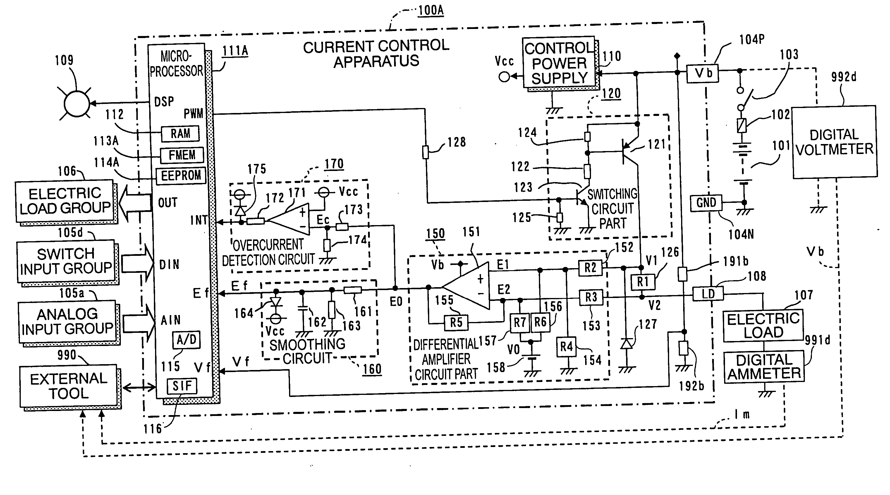
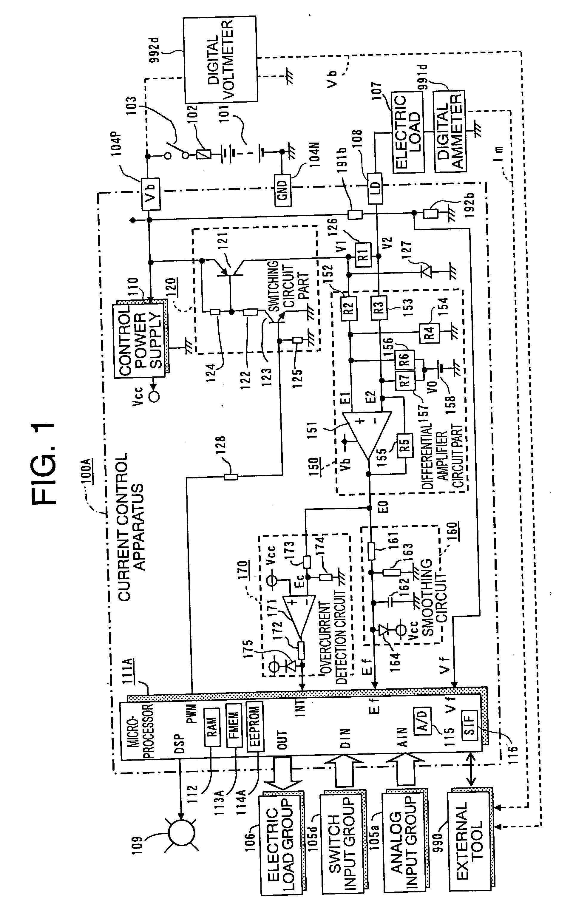
[0231]FIG. 5 is a circuit block diagram that shows the overall construction of a current control apparatus for an electric load according to the second embodiment of the present invention, and the parts or components same as those described above (FIG. 1) are identified by the same symbols or by the same...

embodiment 3

[0291] Although in the above-mentioned second embodiment (see FIG. 5), the power supply monitoring voltage Vf detected by the power supply voltage measuring circuit (the voltage dividing resistors 191b, 192b) is input to the microprocessor 111B, the average measured voltage Ea may instead be input to a microprocessor 111C as the average monitored voltage Va, as shown in FIG. 7.

[0292]FIG. 7 is a circuit block diagram that shows the overall construction of a current control apparatus for an electric load according to a third embodiment of the present invention, and the same parts or components as those described above (FIG. 5) are identified by the same symbols or by the same symbols with “C” affixed to their ends, while omitting a detailed explanation thereof.

[0293] In FIG. 7, a current control apparatus 100C includes, similar to the one as described above, a microprocessor 111C which is fed with electric power from a control power supply 110, a switching circuit part 120, a differ...


PUM

PropertyMeasurementUnit
voltagesaaaaaaaaaa
voltagesaaaaaaaaaa
voltageaaaaaaaaaa

Abstract

A current control apparatus for an electric load can prevent burnout at a short-circuit accident with high control precision. A switching element is interrupted by an overcurrent detection circuit upon occurrence of a load short circuit, but is transitionally limited in current by a current detection resistor. A differential amplifier amplifies a difference voltage between voltages at opposite ends of the current detection resistor to generate a monitored voltage Ef corresponding to a load current. A microprocessor controls the energization rate of the switching element so as to make an estimated load current Ime calculated from the monitored voltage Ef coincide with a target load current Is, and it calculates, upon calibration operation, calibration constants and estimates, during actual operation, a load current Ime from the monitored voltage Ef using the calibration constants.

Description

BACKGROUND OF THE INVENTION [0001] 1. Field of the Invention [0002] The present invention relates to a current control apparatus for an inductive electric load used, for instance, in a vehicle-mounted electronic control system, and more particularly, it relates to such a current control apparatus for an electric load that serves to prevent the burnout of the apparatus due to a short circuit of the load or the like for improved current control accuracy. [0003] 2. Description of the Related Art [0004] In conventional current control apparatuses for an electric load, there have been known a variety of such ones in which the switching energization rate of a switching element connected between a drive power supply and the electric load is controlled in such a manner that the current detected by a current detection resistor is made equal to a target load current to be supplied. Such a kind of electric load current control apparatus is used to control a current supplied to a linear solenoi...

Claims


Application Information

Patent Timeline
Patent Type & Authority Applications(United States)
IPC IPC(8): G05F1/00H02P25/06H01F7/18
CPCF02D41/20F02D41/22F02D2041/2027F02D2041/2058F02D2041/2093H01F7/1844H03K17/0826Y02T10/40
Inventor MATSUMOTO, SHUUITINISHIZAKI, HIROYOSHIFUJIWARA, TAKESHI
Owner MITSUBISHI ELECTRIC CORP
Why Eureka
Try Eureka