
Method and device for treating ailments of the spine

a technology for spine ailments and devices, applied in the field of spine ailments, can solve the problems of insufficient prosthetic implants, insufficient prosthetic implants, and inability to meet the needs of patients,

Inactive Publication Date: 2006-09-07
QUEENS UNIV OF KINGSTON
View PDF99 Cites 163 Cited by
  • Summary
  • Abstract
  • Description
  • Claims
  • Application Information

AI Technical Summary

Benefits of technology

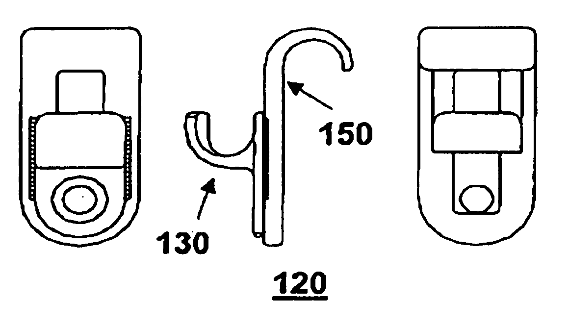
[0010] According to one aspect of the present invention there is provided a spinal facet cap for treating ailments of the spine including scoliosis, comprising a shim portion for inserting into a facet joint of a spine, and an alignment portion for maintaining alignment of said shim po

Problems solved by technology

Apart from the obvious physical deformity, cardiopulmonary problems may also present.
However, if the scoliosis progresses despite such bracing, or if there is substantial discomfort, surgical correction involving fusion of vertebra may be required.
Nevertheless, it is clear that available procedures have drawbacks including the requirement for substantial prosthetic implants (see Mohaideen et al., Pediatr.
Radios—30:110-118 (2000) for a review) and complicated surgical procedures, often only partly correct scoliotic deformities, and result in reduced flexibility of the spine.

Method used


Image

  • Method and device for treating ailments of the spine
  • Method and device for treating ailments of the spine
  • Method and device for treating ailments of the spine

Examples


working examples

Example 1

Cadaveric Implantation

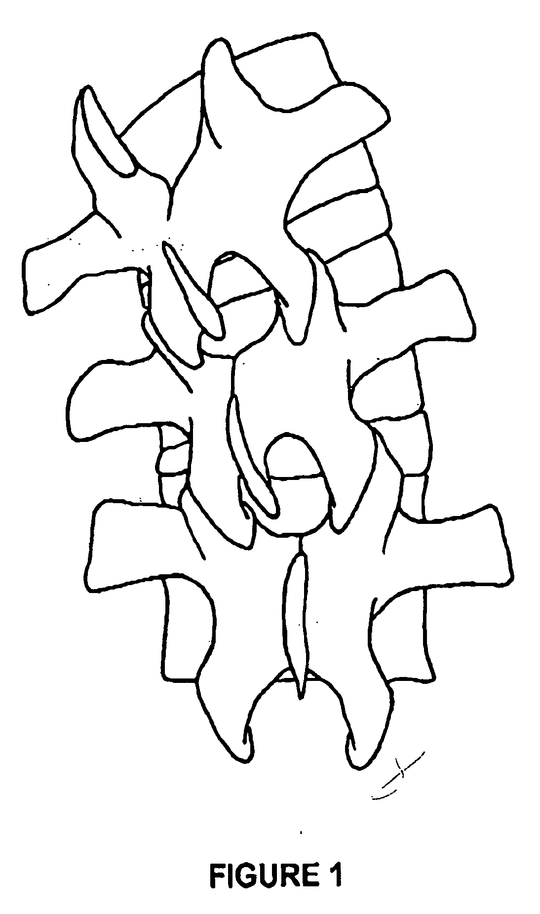
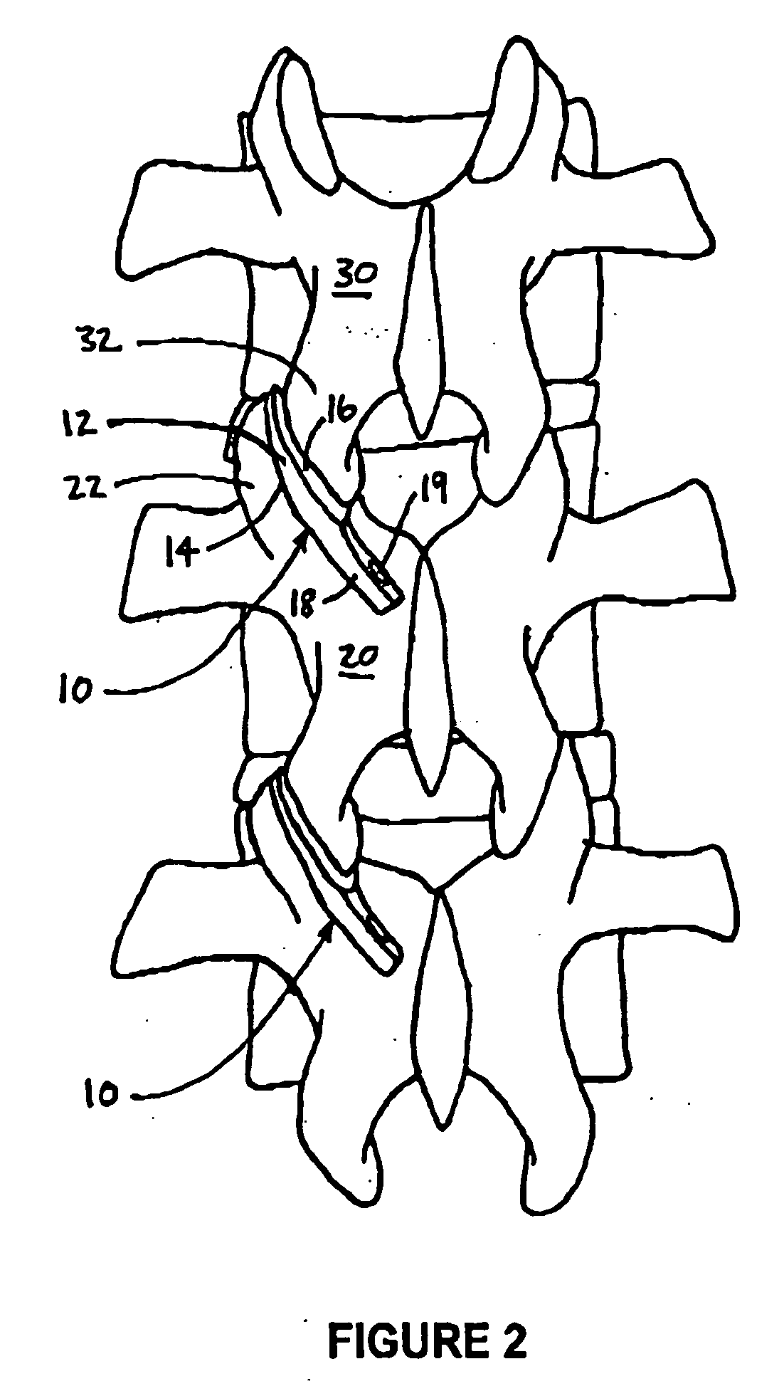
[0058] A spinal facet cap based on the embodiment shown in FIGS. 2 and 3A, having a diameter of about 12 mm, was surgically implanted into the scoliotic spine of a cadaver (female, elderly) at the Department of Anatomy and Cell Biology at Queen's University, Kingston, Ontario, Canada, to evaluate the ease or difficulty of placement and the seating of the facet cap in the facet joint. There were no complications in implanting the facet cap into the spine, suggesting that use of the facet cap for treating scoliosis could become a routine surgical procedure. Moreover, during this exercise it was found that seating of the facet cap in the facet joint was fully satisfactory. This exercise therefore provides a strong indication that the spinal facet cap of the invention will be effective in the treatment of scoliosis.

example 2

Prosthetic Model

[0059] Osteotomies were performed on the mid-lumbar facets of a prosthetic model of an adult human spine to create a scoliotic model. This is shown in the radiograph of FIG. 8A, where reference numeral 200 refers to pins used to hold the model together. Spinal facet caps like that shown in FIG. 3F were then inserted into the mid-lumbar facet joints, which substantially corrected the scoliotic curvature of the spine. This can be seen in the radiograph of Figure BB, where reference numeral 210 refers to the facet caps.

example 3

Formulation of in vivo Placement

[0060] The success of cadaveric implantation led to the formulation of tempo in vivo application. During the course of standard scoliosis surgery, all facet joints from the superior to inferior aspect of the proposed fusion levels are stripped of the joint capsule, the cartilage removed, and the joint decorticated. Prior to destruction of the joints an in vivo model for facet cap placement is present, as no further dissection of the spine is necessary, in which the facet caps can be placed and removed in minutes. This has allowed the formulation of a working model for application of the facet caps. Thus, the below examples relate to the temporary insertion of facet caps during the course of standard corrective surgery, to establish an operative technique for their insertion, and to evaluate their efficacy and ease of use.


PUM


Abstract

This invention relates to a spinal facet cap for treating scoliosis, the facet cap comprising a shim portion for inserting into a facet joint of a spine, and an alignment portion for maintaining alignment of the shim portion within the facet joint. The invention also provides a method for treating scoliosis, comprising implanting at least one spinal facet cap into at least one facet joint of a subject in need thereof.

Description

CLAIM TO PRIORITY [0001] This application is a continuation of U.S. patent application Ser. No. 10 / 075,373, filed on Feb. 15, 2002 which claims the benefit of U.S. Provisional Patent Application No. 60 / 268,860, filed on Feb. 16, 2001, the disclosures of which are incorporated herein by reference in their entirety.BACKGROUND OF THE INVENTION [0002] Scoliosis is an orthopedic condition characterized by abnormal curvature of the spine, with varying degrees of lateral curvature, lordosis and rotation. Despite extensive research, the pathogenesis of scoliosis remains obscure in the majority of cases. [0003] The vertebral column is composed of vertebra, discs, ligaments and muscles. Its function is to provide both mobility and stability of the torso. Mobility includes rotation, lateral bending, extension and flexion. Scoliotic curvature is associated with pathologic changes in the vertebra and related structures. Vertebral bodies become wedge-shaped, pedicles and laminas become shorter an...

Claims


Application Information

Patent Timeline
IPC IPC(8): A61F2/30A61B17/70A61F2/00A61F2/02A61F2/44
CPCA61B17/7064A61F2/4405A61F2002/30522A61F2002/3055A61F2220/0025A61F2250/0007
Inventor SOBOLESKI, DONALD A.SAUNDERS, GERALD A. B.BORSCHNECK, DANIEL P.
Owner QUEENS UNIV OF KINGSTON
Learn More