

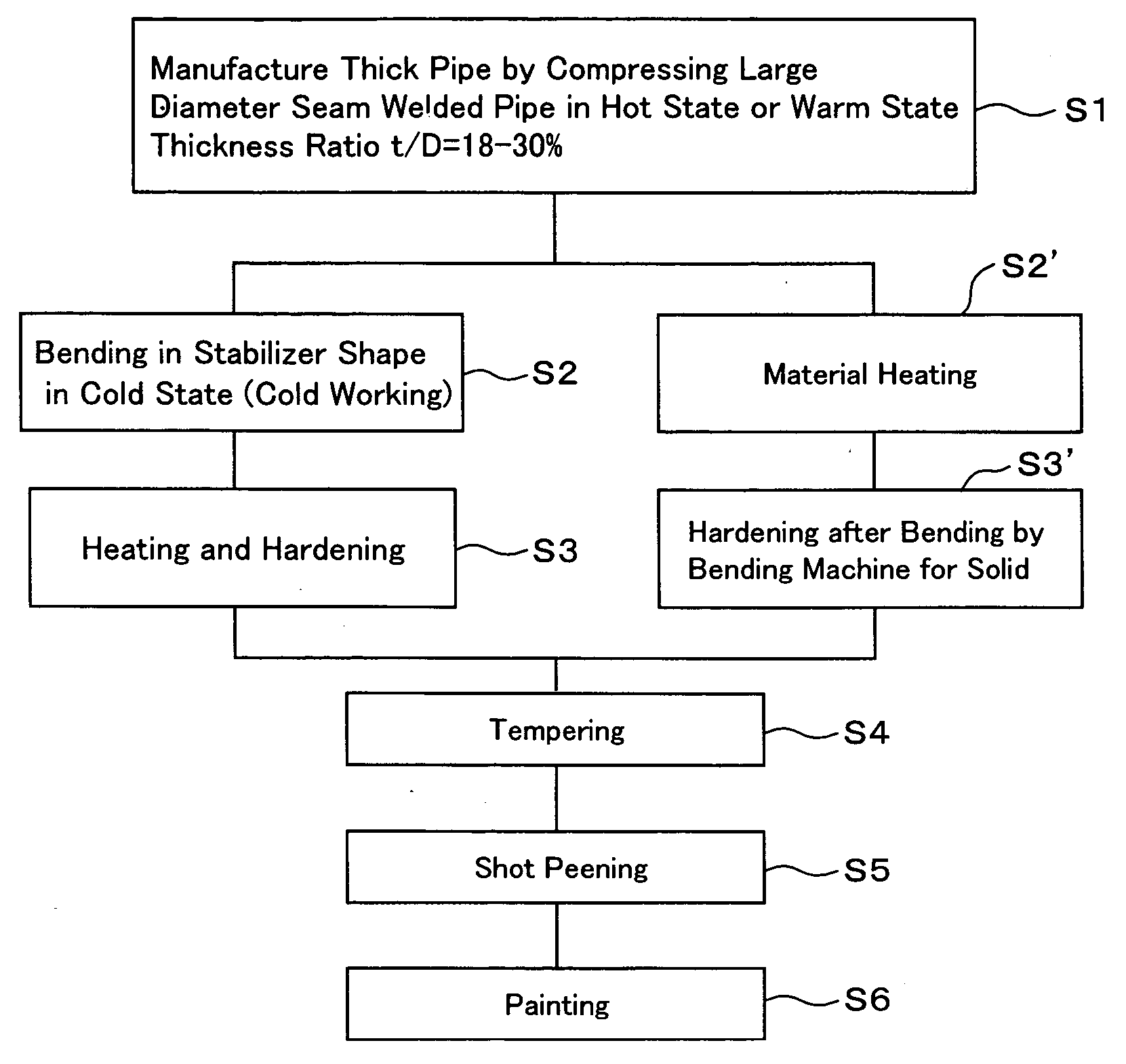
Hollow stabilizer and method of manufacturing the same
a technology of stabilizer and hollow, which is applied in the field of manufacturing a hollow stabilizer, can solve the problems of not being executed very frequently, the inner surface portion becomes a starting point of breakage, and the processing cost of the inner surface shot peening is rather high, so as to achieve satisfactory effect, improve the fatigue strength of the inner surface portion, and improve the fatigue strength
- Summary
- Abstract
- Description
- Claims
- Application Information
AI Technical Summary
Benefits of technology
Problems solved by technology
Method used
Image

Examples
embodiments
Embodiment 1
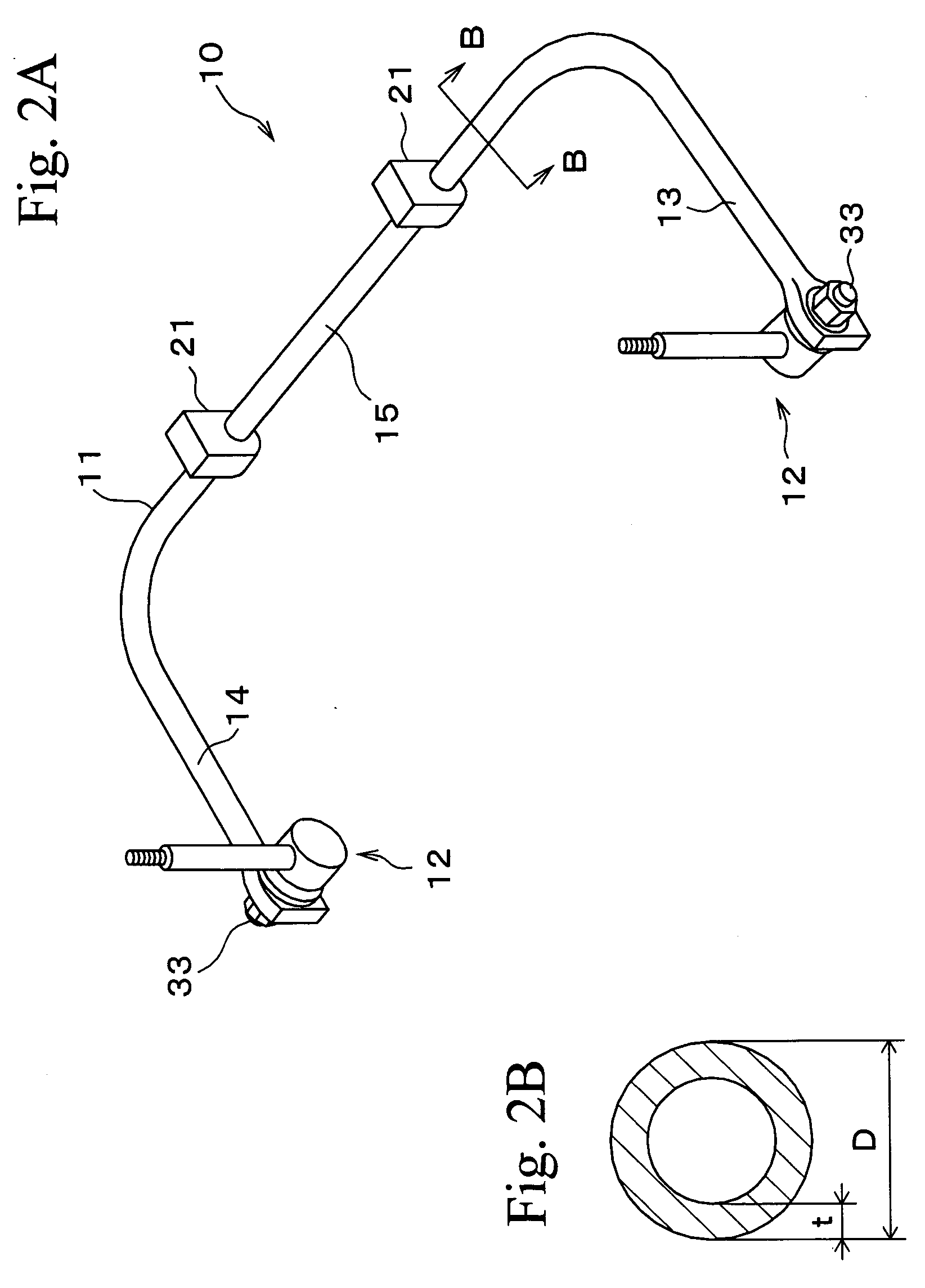
[0038] Next, particular manufactured embodiments are described and further details of the present invention will be given. Table 1 shows respective specifications of a solid stabilizer having a wire diameter of 27 mm, and a hollow stabilizer having substantially the same spring constant as that of the solid stabilizer. In this case, the respective stabilizers are structured such that the heat treatment, the shot peening, and the coating are applied. Further more, main stresses at the time of imparting a deformation of the same stroke to the respective stabilizers are also described in Table 1, and the values are shown in FIG. 3.
TABLE 1ThicknessSpringMain Stress atMain Stress atRatioConstantOuter SurfaceInner SurfaceNoMaterial Size(t / D)(N / mm)Portion (MPa)Portion (MPa)1Solid, Diameter27—25.1365—2Diameter30.0 × t3.511.7%24.95914583Diameter28.6 × t4.716.4%24.84993394Diameter28.0 × t5.519.6%25.24753045Diameter27.2 × t7.527.6%25.1430229
t: thickness
[0039] A sample No. 2 is ...
embodiment 2
[0041] A durability test was performed by employing nine hollow stabilizers having outer diameters and thicknesses as shown in Table 2 and solid stabilizers having a diameter of 25 mm. Further more, it was investigated at which of the inner or outer surface portions of the hollow stabilizer the starting point of breakage was generated, a ratio of maximum stresses generated on the inner and outer surfaces (inner surface stress / outer surface stress) is investigated, and the results thereof are also described in Table 2. Further more, a ratio of fatigue life of the hollow stabilizer with respect to a fatigue life of the solid stabilizer and a ratio of mass are calculated, and the results thereof are also described in Table 2. An S-N graph of the hollow stabilizer is shown in FIG. 5.
[0042] As shown in Table 2 and FIG. 5, in the hollow stabilizer in which the thickness ratio is equal to or greater than 20%, all of the starting points of breakage exist in the outer surface portion, and a...
PUM
| Property | Measurement | Unit |
|---|---|---|
| diameter | aaaaa | aaaaa |
| temperature | aaaaa | aaaaa |
| thickness | aaaaa | aaaaa |
Abstract
Description
Claims
Application Information