Illumination optical apparatus and projection exposure apparatus

Active Publication Date: 2006-09-14
NIKON CORP
View PDF101 Cites 165 Cited by
  • Summary
  • Abstract
  • Description
  • Claims
  • Application Information

AI Technical Summary

Benefits of technology

[0022] According to the present embodiments, for example, thicknesses of the birefringent members are set in their respective predetermined distributions, whereby the polarization after passage of the illumination light emitted from the light source, through the plurality of birefringent members, can be, for example, in a state consisting primarily of polarization in the circumferential direction around the optical axis in an annular regi

Problems solved by technology

In effecting the annular illumination by the conventional technology as described above, there was the problem of large loss in quantity of the illumination light to lower illumination efficiency if the polarization state of the illumination light was made to be linear polarization substantially matched with the circumferential direction of the annular region on the pupil plane of the illumination optical system.
This method used only energy in the predetermined linear polarization component out of the energy of the illumination light of random polarization, i.e., only approximately half energy as the illumin

Method used


Image

  • Illumination optical apparatus and projection exposure apparatus
  • Illumination optical apparatus and projection exposure apparatus
  • Illumination optical apparatus and projection exposure apparatus

Examples


Embodiment Construction

[0048] An example of preferred embodiment of the present invention will be described below with reference to the drawings. The present example is an application of the present invention to a case where exposure is performed by a projection exposure apparatus of the scanning exposure type (scanning stepper) according to the step-and-scan method.

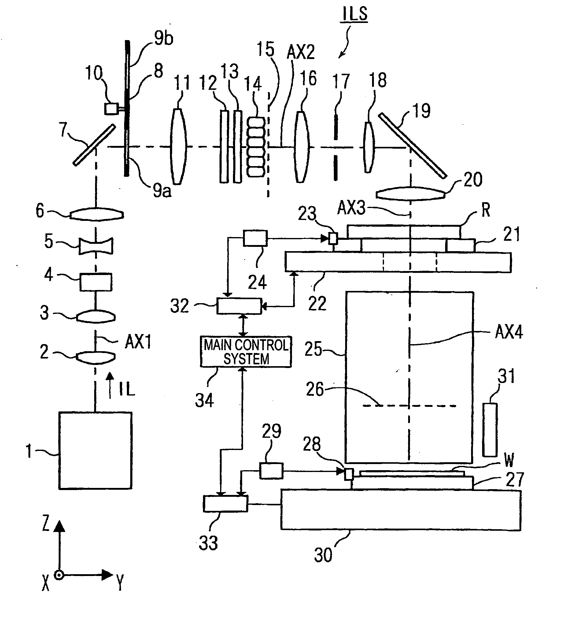
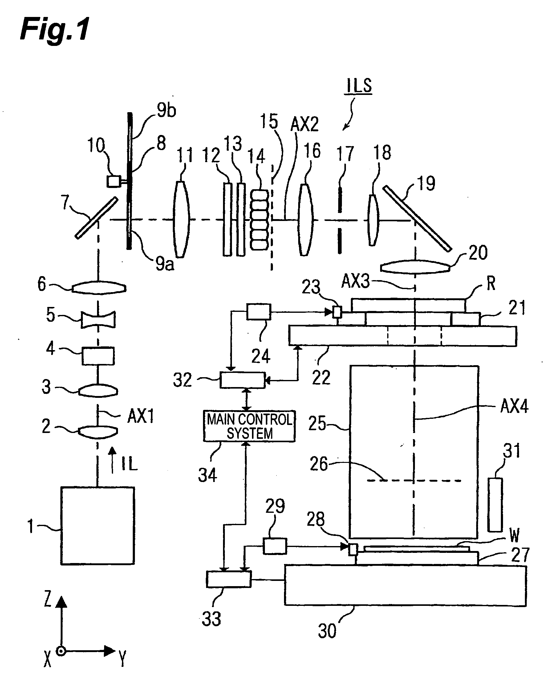
[0049]FIG. 1 is a drawing showing a schematic configuration of the projection exposure apparatus of the present example partly cut, and in this FIG. 1 the projection exposure apparatus of the present example is provided with an illumination optical system ILS and a projection optical system 25. The former illumination optical system ILS is provided with a plurality of optical members arranged along the optical axis (optical axis of illumination system) AX1, AX2, AX3 from an exposure light source 1 (light source) to a condenser lens 20 (the details of which will be described later), and illuminates an illumination field on a pattern surface (r...


PUM


Abstract

An illumination optical apparatus and projection exposure apparatus capable of reducing a light quantity loss when a mask is illuminated with a polarized illumination light. An illumination optical system for illuminating a reticle with an illumination light and a projection optical system for projecting the pattern image of the reticle onto a wafer are provided. An illumination light emitted from an exposure light source in a linearly polarized state in the illumination optical system passes through first and second birefringent members having different fast axis directions and is converted into a polarized state that is substantially linearly polarized in a circumferential direction with the optical axis as the center in an almost specific annular area, and them illuminates the reticle under an annular illuminating condition after passing through a fly-eye lens.

Description

CROSS-REFERENCE TO RELATED APPLICATIONS [0001] This is a continuation-in-part application of application serial no. PCT / JP2004 / 015853 filed on Oct. 26, 2004, now pending.BACKGROUND OF THE INVENTION [0002] 1. Field of the Invention [0003] The present invention relates to illumination technology and exposure technology used in the lithography step for fabricating various devices, e.g., semiconductor integrated circuits (LSI and the like), image pickup devices, or liquid crystal displays and, more particularly, to illumination technology and exposure technology for illuminating a mask pattern with light in a predetermined polarization state. Furthermore, the present invention relates to device fabrication technology using the exposure technology. [0004] 2. Related Background Art [0005] For forming microscopic patterns of electronic devices such as semiconductor integrated circuits or liquid crystal displays, a method adopted is to project a demagnified image of a pattern on a reticle (...

Claims


Application Information

Patent Timeline
IPC IPC(8): G03B27/52G02B19/00G03F7/20H01L21/027
CPCG02B27/28G03F7/70108G03F7/70966G03F7/70191G03F7/70566G03F7/70158G02B5/3083G02B27/286G03F7/70341
Inventor SHIRAISHI, NAOMASA
Owner NIKON CORP
Why Eureka
Try Eureka