Battery cartridge-connecting system for battery module

Active Publication Date: 2006-09-28
LG ENERGY SOLUTION LTD
View PDF7 Cites 52 Cited by
  • Summary
  • Abstract
  • Description
  • Claims
  • Application Information

AI Technical Summary

Benefits of technology

[0010] Specifically, it is a first object of the present invention to provide a battery cartridge-connecting system that is capable of easily accomplishing the electrical connection and the mechanical coupling in a compact-structured battery module or battery system, the battery cartridge-connection system having excellent electrical characteristics, such as electric resistance at the connected parts, after the electrical connection is completed, and excellent mechanical strength to external impacts or vibrations after the mechanical coupling is completed. The excellent electrical characteristics and the excellent mechanical strength may be also applied to the mounting and the electrical connection of a printed circuit board (PCB), which is provided to electrically connect battery cartridges having unit cells mounted therein and measure the voltage and temperature of the unit cells.
[0011] I

Problems solved by technology

As the unit cell for the medium- or large-sized battery system is widely used a pouch-shaped secondary cell, which is generally packaged in a battery case made of a laminate sheet consisting of aluminum and polymer resin, and therefore, the mechanical strength of the pouch-shaped secondary cell is not high.
However, the closed type battery module has problems in that heat generated in unit cells is accumulated, and the accumulated heat accelerates the deterioration of the cells and that a small or large number of unit cells are overheated when they are operated abnormally, and therefore, the unit cells may catch on fire or explode.
When such

Method used


Image

  • Battery cartridge-connecting system for battery module
  • Battery cartridge-connecting system for battery module
  • Battery cartridge-connecting system for battery module

Examples


Embodiment Construction

[0049] Now, preferred embodiments of the present invention will be described in detail with reference to the accompanying drawings. It should be noted, however, that the scope of the present invention is not limited by the illustrated embodiments.

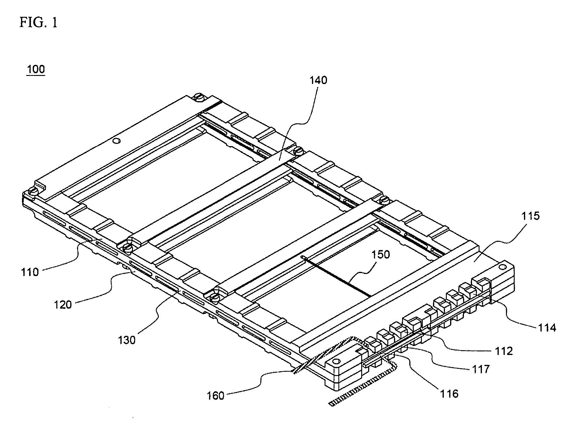
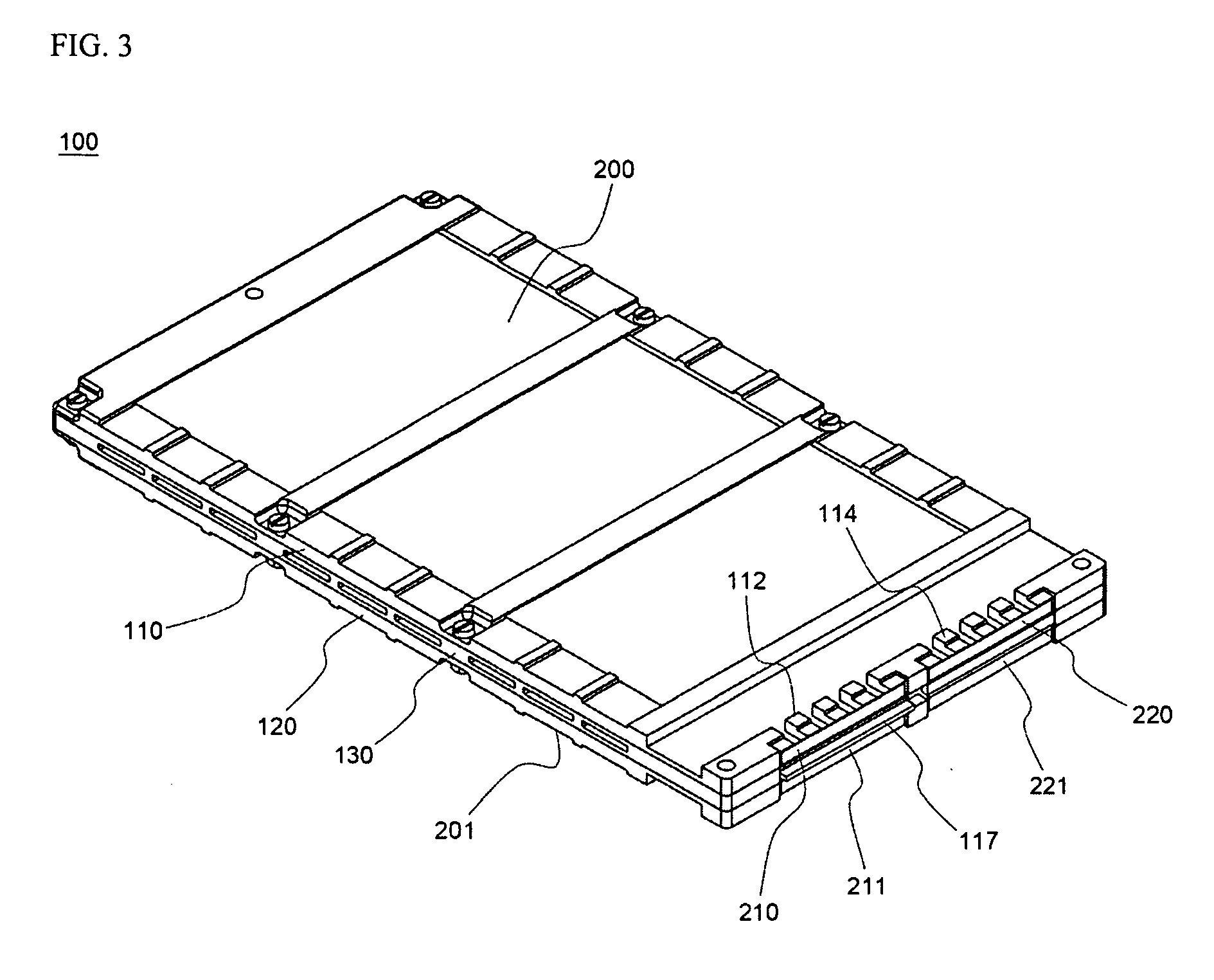
[0050]FIG. 1 is a perspective view typically illustrating a battery cartridge according to a preferred embodiment, which can be used in the present invention.

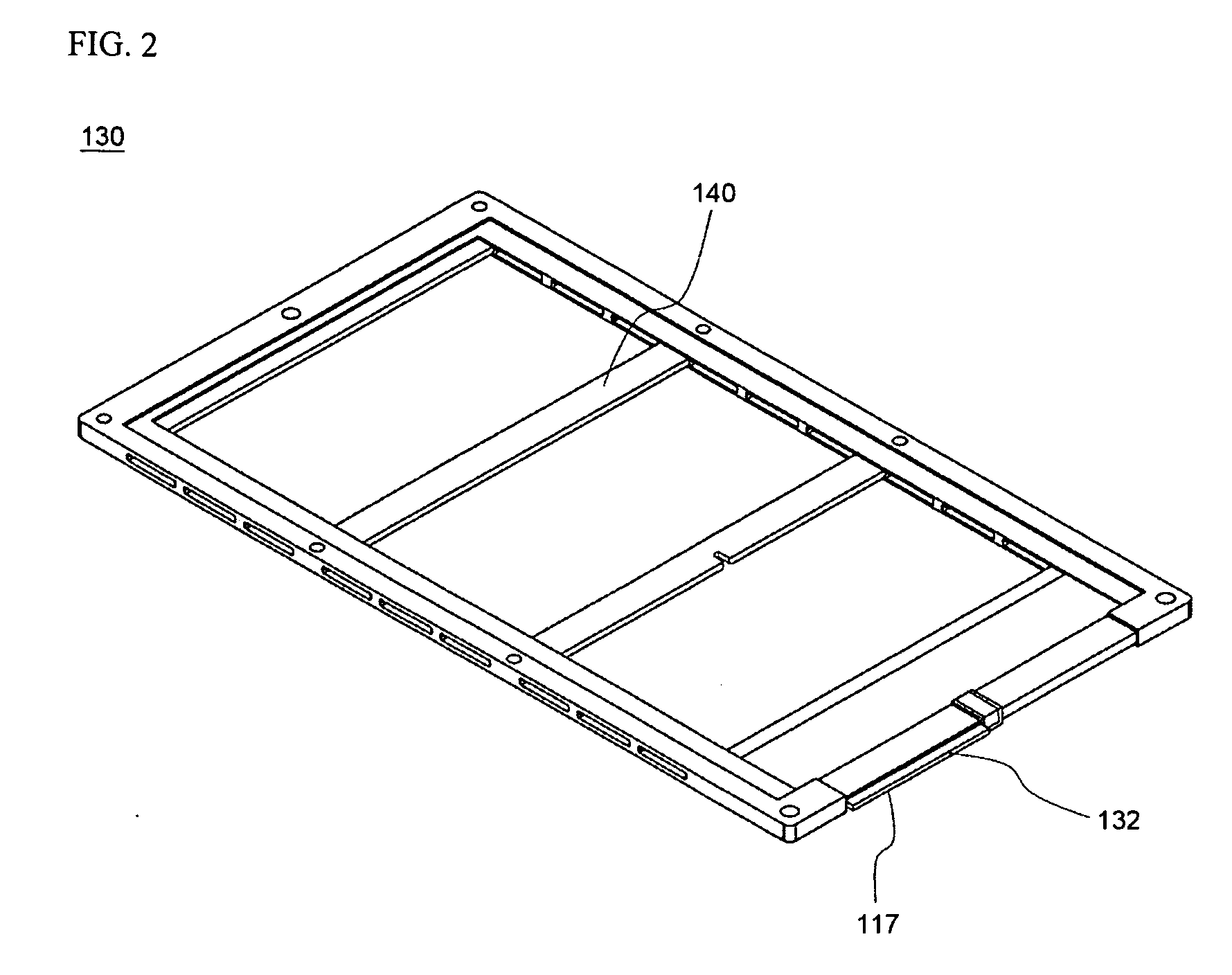
[0051] Referring to FIG. 1, the battery cartridge 100 comprises: a pair of outer frame members 110 and 120; and an inner frame member 130 disposed between the outer frame members 110 and 120. The details of the frame members 110, 120, and 1300 are disclosed in Korean Patent Application No. 2004-111699, which has been filed in the name of the applicant of the present application.

[0052] Two unit cells (not shown) are mounted in a hollow part between the first outer frame member 110 and the inner frame member 130 and in another hollow part between the second outer frame member 120 and ...


PUM


Abstract

Disclosed herein is a battery cartridge-connecting system for battery modules, comprising: bus bars, each of which includes a plate-shaped bar body, coupling parts, and electrical connection parts; a base plate, to which the bus bars are easily mounted; and a printed circuit board (PCB), which is easily coupled to the bus bars and is mounted to the base plate in a compact structure. The present invention also provides a battery module and a medium- or large-sized battery system including the battery cartridge-connecting system. According to the present invention, the battery cartridge-connecting system easily accomplishes the electrical connection and the mechanical coupling in the compact-structured battery module or battery system. In addition, the battery cartridge-connection system has excellent electrical characteristics, such as electric resistance at the connected parts, after the electrical connection is completed, and excellent mechanical strength to external impacts or vibrations after the mechanical coupling is completed. Furthermore, the battery cartridge-connecting system prevents a risk of an engineer or a user being exposed to the electrical short circuits when the battery module or the battery system is manufactured or when the battery module or the battery system is repaired.

Description

FIELD OF THE INVENTION [0001] The present invention relates to a battery cartridge-connecting system for battery modules, and, more particularly, to a battery cartridge-connecting system for battery modules, comprising: bus bars, each of which includes a plate-shaped bar body, coupling parts, and electrical connection parts; a base plate, to which the bus bars are easily mounted; and a printed circuit board (PCB), which is easily coupled to the bus bars and is mounted to the base plate in a compact structure, and a battery module and a medium- or large-sized battery system including the same. BACKGROUND OF THE INVENTION [0002] Recently, a secondary battery, which can be charged and discharged, has been widely used as an energy source for wireless mobile devices. Also, the secondary battery has attracted considerable attention as a power source for electric vehicles and hybrid electric vehicles, which have been developed to solve problems, such as air pollution, caused by existing ga...

Claims


Application Information

Patent Timeline
IPC IPC(8): H02J7/00H01M50/211H01M50/244H01M50/249H01M50/264H01M50/507H01M50/516H01M50/519H01M50/528
CPCH01M2/1061H01M2/1077H01M2/206H01M10/052H01M10/482H01M10/486Y02E60/122Y02T10/7011Y02E60/10H01M50/249H01M50/519H01M50/507H01M50/516H01M50/264H01M50/244H01M50/211H01M50/20Y02T10/70
Inventor YOON, JUNILLRO, JONG-YULJUNG, DO YANGYU, JISANG
Owner LG ENERGY SOLUTION LTD
Why Eureka
Try Eureka