
Active diagnostic interface for wafer probe applications

a technology of active diagnostic interface and wafer probe, which is applied in the direction of individual semiconductor device testing, semiconductor/solid-state device testing/measurement, instruments, etc., can solve the problems of system unnecessary and time-consuming, and the controller of the test system is a significant cost factor in the test system, so as to achieve the effect of confirming operation more quickly

Inactive Publication Date: 2006-09-28
FORMFACTOR INC
View PDF15 Cites 14 Cited by
  • Summary
  • Abstract
  • Description
  • Claims
  • Application Information

AI Technical Summary

Benefits of technology

[0014] In accordance with the present invention, monitoring of test signals is provided between the test system controller and one or more DUTs during testing. Such monitoring enables confirmation of test results from at least one DUT. Such monitoring further provides a number of features including—(1) ensuring that the test system controller is functioning properly, (2) enabling a test operator to verify operation more rapidly rather than waiting for a compilation of data from the test system controller, and (3) enabling a test operator to monitor a particular DUT quickly which is posing problems or so that modifications can be made on the particular DUT and confirmed before similar modifications are made to the remaining DUTs on a wafer.
[0015] Monitoring of test signals is provided by including a diagnostic interface connection on the PCB of the probe card. The diagnostic interface includes a connector that contacts the channel lines provided to one or more of the particular DUTs. The diagnostic interface connection to the PCB of the probe card allows signals to be brought out from a convenient position to connect to a user interface such as a personal computer. To prevent signal distortion in test signals on the channel lines due to long lines of the diagnostic interface, in one embodiment buffers are provided on the PCB as part of the interface connector connecting to the channels.

Problems solved by technology

The ATE test system controller is a significant cost factor in a test system, and includes equipment to generate test signals on channels to provide to contact pads on multiple DUTs.
Probe cards, serving as an interface between a test system controller and a wafer, are typically much less expensive than a test system controller, and typically replaced after a much shorter lifecycle than the test system controller due to wear of probes on the probe card.
In another instance, tests from only one DUT may be desired to indicate repairs needed to one or more of the DUTs, since taking time to receive and process results from all DUTs connected to a test system may be unnecessary and time consuming.

Method used


Image

  • Active diagnostic interface for wafer probe applications
  • Active diagnostic interface for wafer probe applications
  • Active diagnostic interface for wafer probe applications

Examples


Embodiment Construction

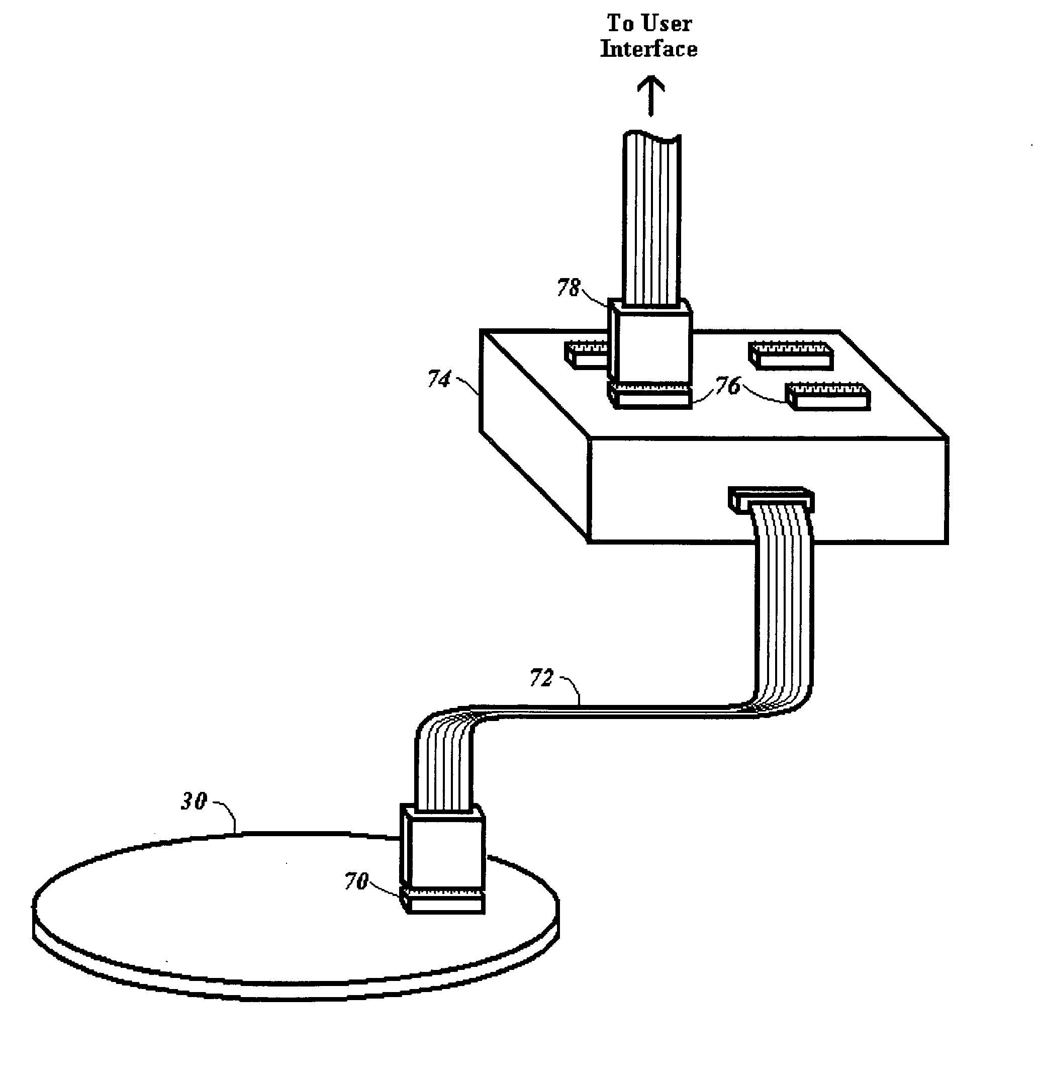
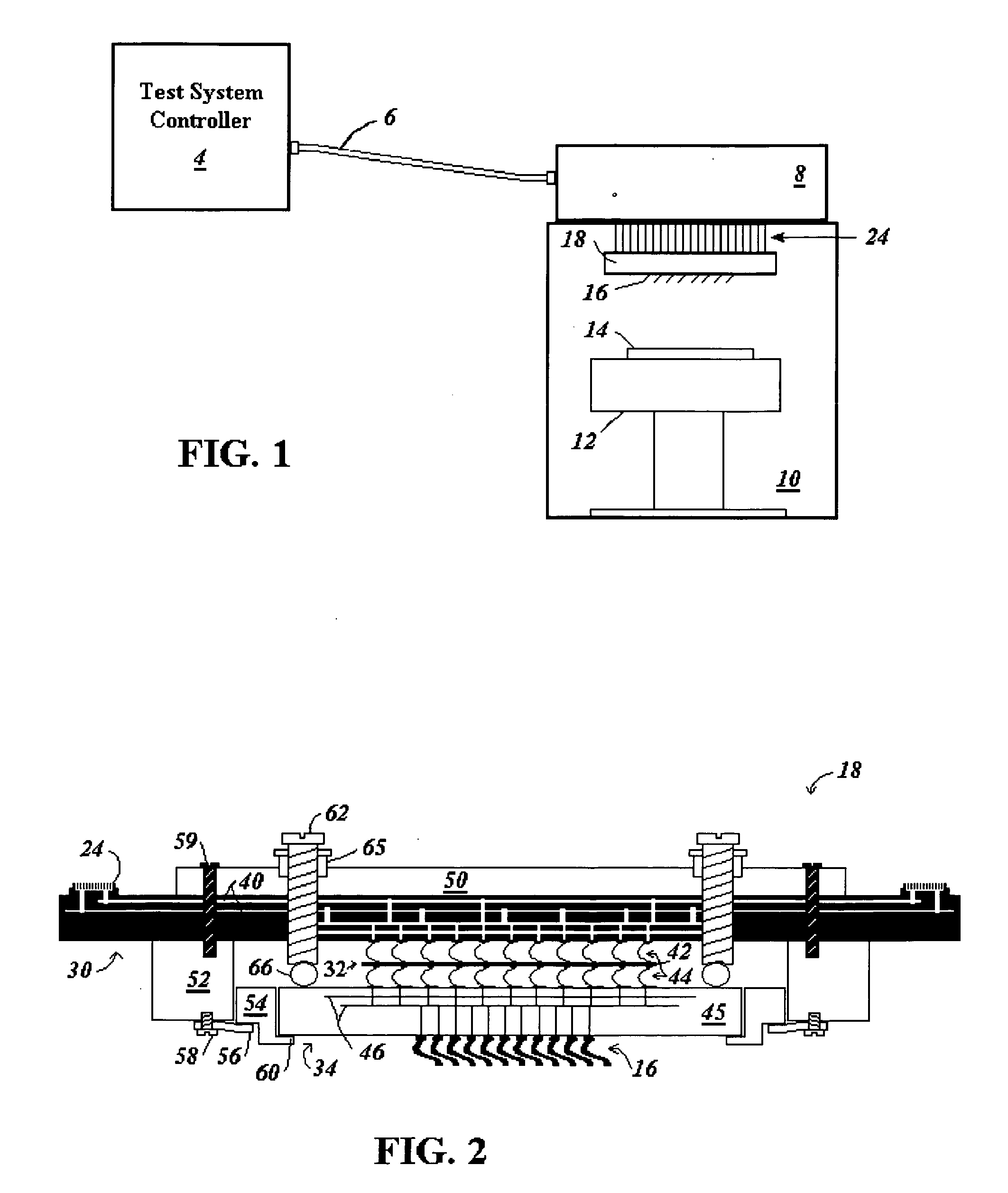
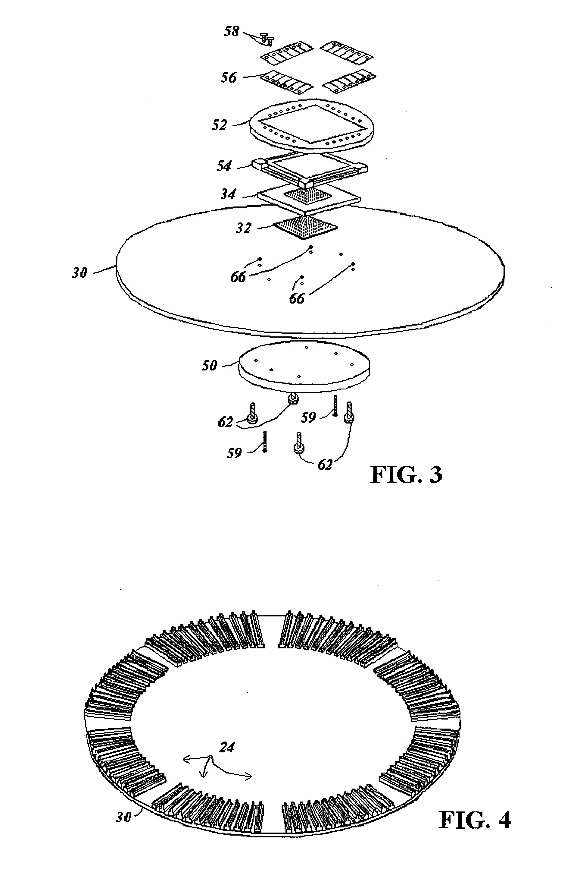
[0026]FIG. 5 shows a perspective view of components of test system with a diagnostic interface according to the present invention. As shown, the diagnostic interface includes a connector 70 attached to the PCB 30 of a probe card. The test head connectors 24 adjacent to the connector 70 on the PCB 30 are not shown in FIG. 5. The diagnostic interface connector 70 includes connections to channel lines 40 in the PCB 30 that carry signals between a test system controller and probes for connecting to one or more DUTs. The components of the probe card apart from the diagnostic interface connector 70 to the PCB 30 remain the same, with reference to FIG. 2 including channel lines 40 of the PCB 30 linking through an interposer 32 and space transformer 34 to probes 16 for contacting to DUTs on a wafer.

[0027] The diagnostic interface connector 70 is preferably a fine pitch impedance controlled socket that may be a pogo pin type connector, a ZIF connector, or other vertical interface connector ...


PUM


Abstract

A diagnostic interface on a wafer probe card is provided to enable monitoring of test signals provided between the test system controller and one or more DUTs on a wafer during wafer testing. To prevent distortion of test signals on the channel lines, in one embodiment buffers are provided on the probe card as part of the diagnostic interface connecting to the channels. In another embodiment, an interface adapter pod is provided that connects to the diagnostic interface on the probe card to process the test results and provide the results to a user interface such as a personal computer.

Description

BACKGROUND [0001] 1. Technical Field [0002] The present invention relates to an interface for monitoring test signals provided to and from a probe card used for contacting and testing devices under test (DUTs) on a wafer. [0003] 2. Related Art [0004] Test systems for testing DUTs on wafers during manufacture typically include an Automatic Test Equipment (ATE) tester or test system controller, and a probe card for connecting channels from the test system controller to DUTs on a wafer. A conventional test system is shown in FIG. 1, and described in more detail subsequently. [0005] The ATE test system controller is a significant cost factor in a test system, and includes equipment to generate test signals on channels to provide to contact pads on multiple DUTs. The test system controller further receives and analyzes responses from the DUTs. Test results for all DUTs on a wafer are displayed by the test system controller on a user interface. [0006] The probe cards that carry signals be...

Claims


Application Information

Patent Timeline
IPC IPC(8): G01R31/26
CPCG01R31/2831G01R31/2889G01R31/26H01L22/00G01R1/067
Inventor HENSON, ROY J.CHRAFT, MATTHEW E.
Owner FORMFACTOR INC
Learn More