Photodiode with controlled current leakage

a photodiode and current leakage technology, applied in the field of radioactive detectors, can solve the problems of many resources associated with the use of conventional photodiodes, waste of capital, time and manpower, leakage current, etc., and achieve the effects of reducing the leakage current of a photodiode, increasing the signal-to-noise ratio and sensitivity, and aggressive and effective techniques for controlling leakage curren

Active Publication Date: 2006-10-05
OSI OPTOELECTRONICS
View PDF33 Cites 57 Cited by
  • Summary
  • Abstract
  • Description
  • Claims
  • Application Information

AI Technical Summary

Benefits of technology

[0023] It is an object of the present invention to design and manufacture photodiodes with controlled leakage current. More specifically, the present invention provides low-voltage, low-power photodiodes with aggressive and effective techniques for controlli

Problems solved by technology

Conventional photodiodes, as described above, still present numerous problems in their use today.
Many of the resources associated with the use of conventional photodiodes, including capital, time, and manpower are wasted in resolving some of the numerous problems including controlling (also referred to as modifying, managing, reducing or eliminating) photodiode leakage current, noise, and stray light.
In addition, there are secondary problems that pose problems in conventional photodiode use.
A particularly serious problem associated with conventional photodiodes is leakage current.
Leakage current is a major source of signal offset and noise in applications operating in current mode.
Leakage current is temperature dependent; thus, an increase in temperature and reverse bias results in an increase in leakage or dark current.
In addition to leakage current, noise is often a limiting factor for the performance of any device or system.
In almost every area of measurement, the limit to the detectability of signals is set by noise, or unwanted signals that obscure the desired signal.
Noise issues generally have an important effect on device or system cost.
Conventional photodiodes are particularly sensitive to noise issues.
These noise components collectively contribute to the total noise in the photodiode.
Shot noise tends to dominate when the photodiode is used in photoconductive mode where an external reverse bias is applied across the device.
As an example, detector noise generated by a planar diffused photodiode operating in the reverse bias mode is a combination of both shot

Method used


Image

  • Photodiode with controlled current leakage
  • Photodiode with controlled current leakage
  • Photodiode with controlled current leakage

Examples


Embodiment Construction

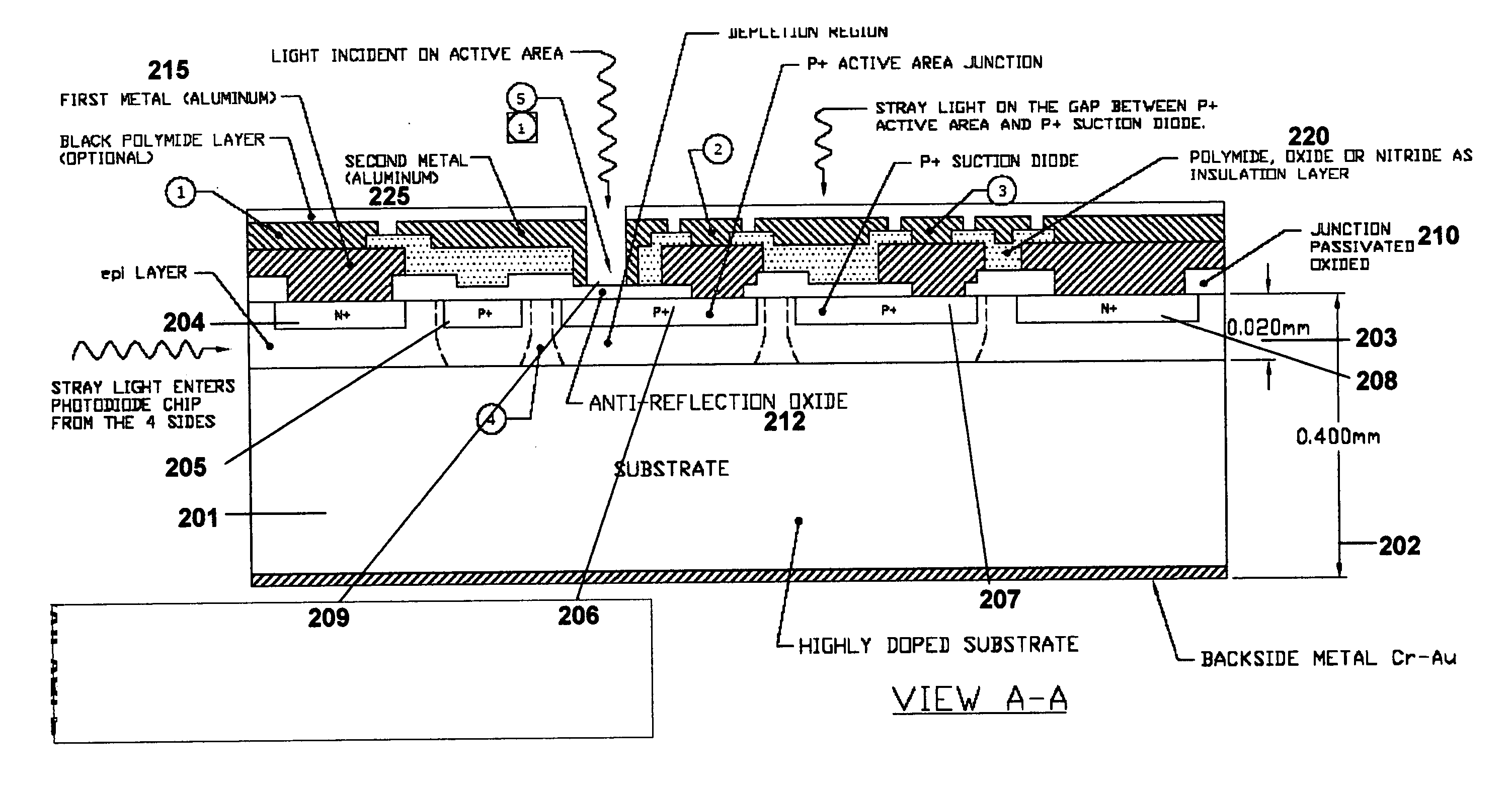
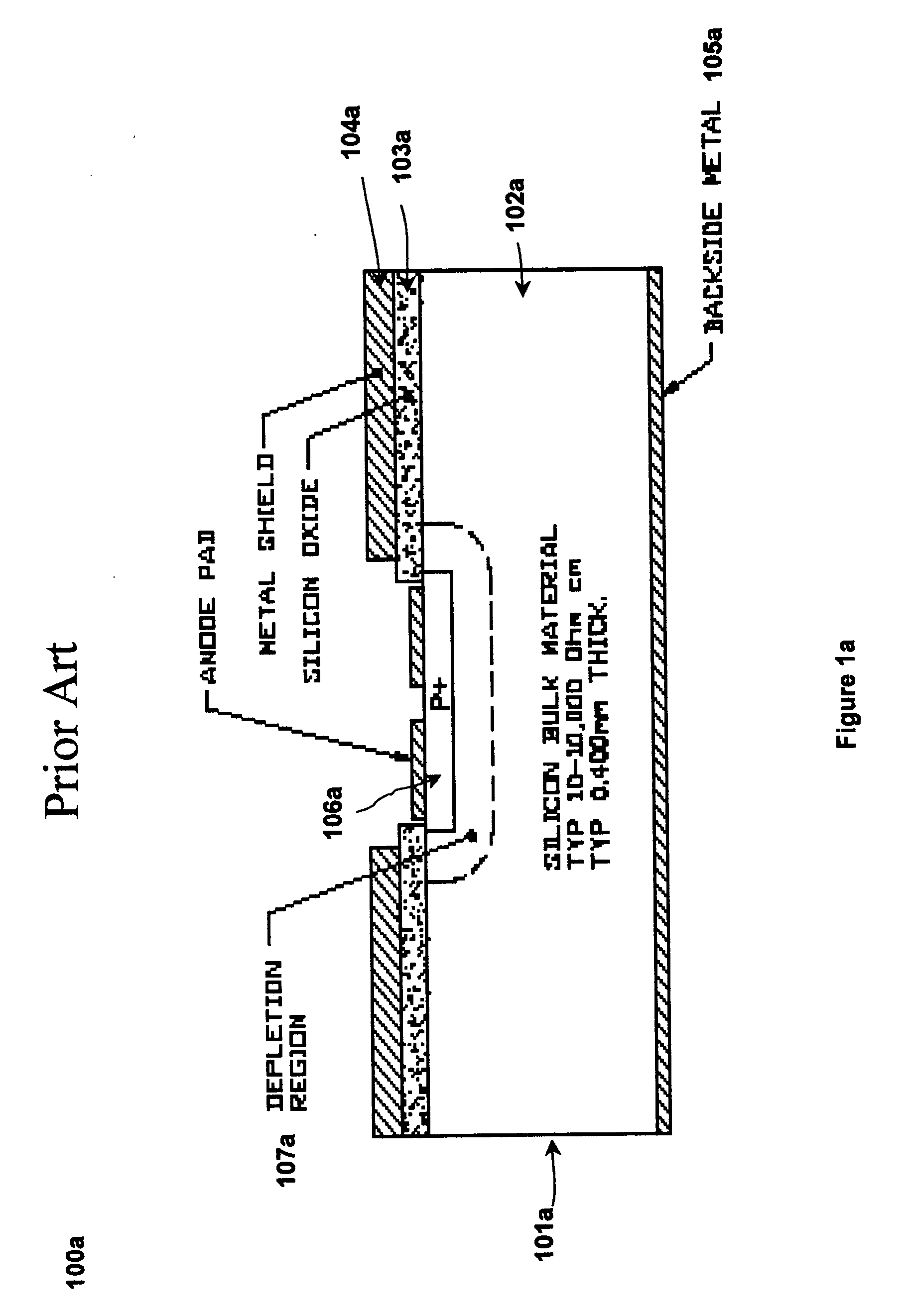
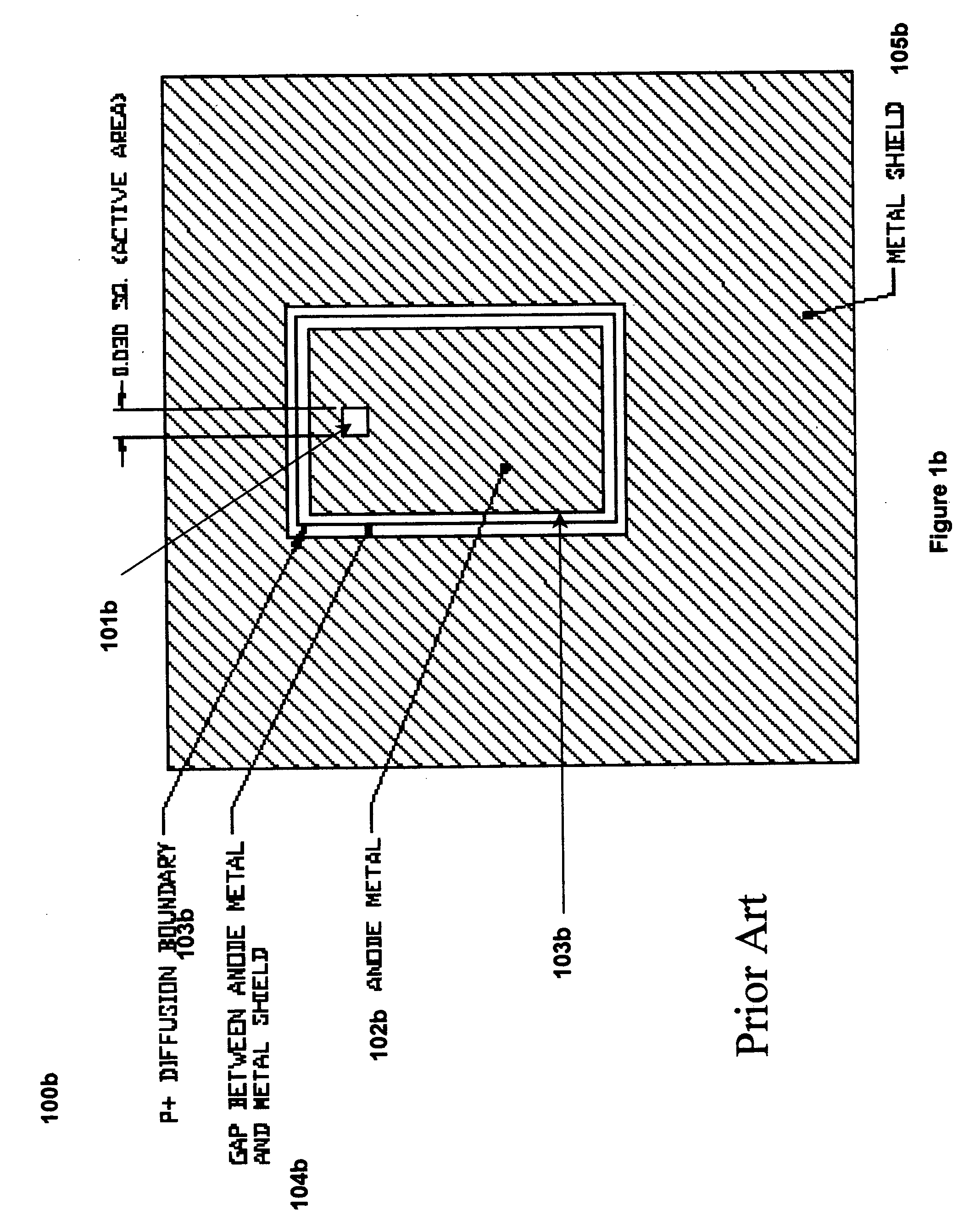
[0038] The present invention is directed towards radiation detectors and methods of detecting incident radiation. In particular the present invention is directed towards photodiodes with controlled current leakage detector structures and a method of manufacturing photodiodes with controlled current leakage detector structures. More specifically, the present invention discloses photodiodes with special structures to substantially reduce detection of stray light. Additionally, the present invention gives special emphasis to design, fabrication, and use of photodiodes with controlled leakage current.

[0039] Various modifications to the preferred embodiment, disclosed herein, will be readily apparent to those of ordinary skill in the art and the disclosure set forth herein may be applicable to other embodiments and applications without departing from the spirit and scope of the present invention and the claims hereto appended. Thus, the present invention is not intended to be limited to...


PUM


Abstract

The present invention is directed towards radiation detectors and methods of detecting incident radiation. In particular the present invention is directed towards photodiodes with controlled current leakage detector structures and a method of manufacturing photodiodes with controlled current leakage detector structures. The photodiodes of the present invention are advantageous in that they have special structures to substantially reduce detection of stray light. Additionally, the present invention gives special emphasis to the design, fabrication, and use of photodiodes with controlled leakage current.

Description

FIELD OF THE INVENTION [0001] The present invention pertains generally to the field of radiation detectors, and in particular, relates to photodiodes with controlled current leakage. BACKGROUND OF THE INVENTION [0002] Certain photodiodes have two-electrode radiation-sensitive junctions formed in semiconductor material. Light, which illuminates the junction, creates charge carriers. Reverse current varies with illumination. Photodiodes can be photovoltaic or photoconductive devices, used for detection of optical power and subsequent conversion to electrical power. [0003] Operationally, photodiodes absorb photons or charged particles, facilitating detection of incident optical power and generating current proportional to the incident power, thus converting the incident optical power to electrical power. Light-induced current of the photodiode corresponds to the signal while “dark” current represents noise. “Dark” current is that current that is not induced by light, or that is present...

Claims


Application Information

Patent Timeline
IPC IPC(8): H01L31/113
CPCH01L27/1446H01L31/02164H01L27/14623
Inventor BUI, PETER STEVENTANEJA, NARAYAN DASS
Owner OSI OPTOELECTRONICS
Why Eureka
Try Eureka