

Fuel Cell
a fuel cell and cell technology, applied in the field of fuel cells, can solve the problems of difficulty in controlling the concentration of methanol in the aqueous solution, the decrease of the fuel concentration in the fuel tank,
- Summary
- Abstract
- Description
- Claims
- Application Information
AI Technical Summary
Benefits of technology
Problems solved by technology
Method used
Image

Examples
first embodiment
[0022] the present invention will be described hereinafter with reference to FIGS. 1 through 3.
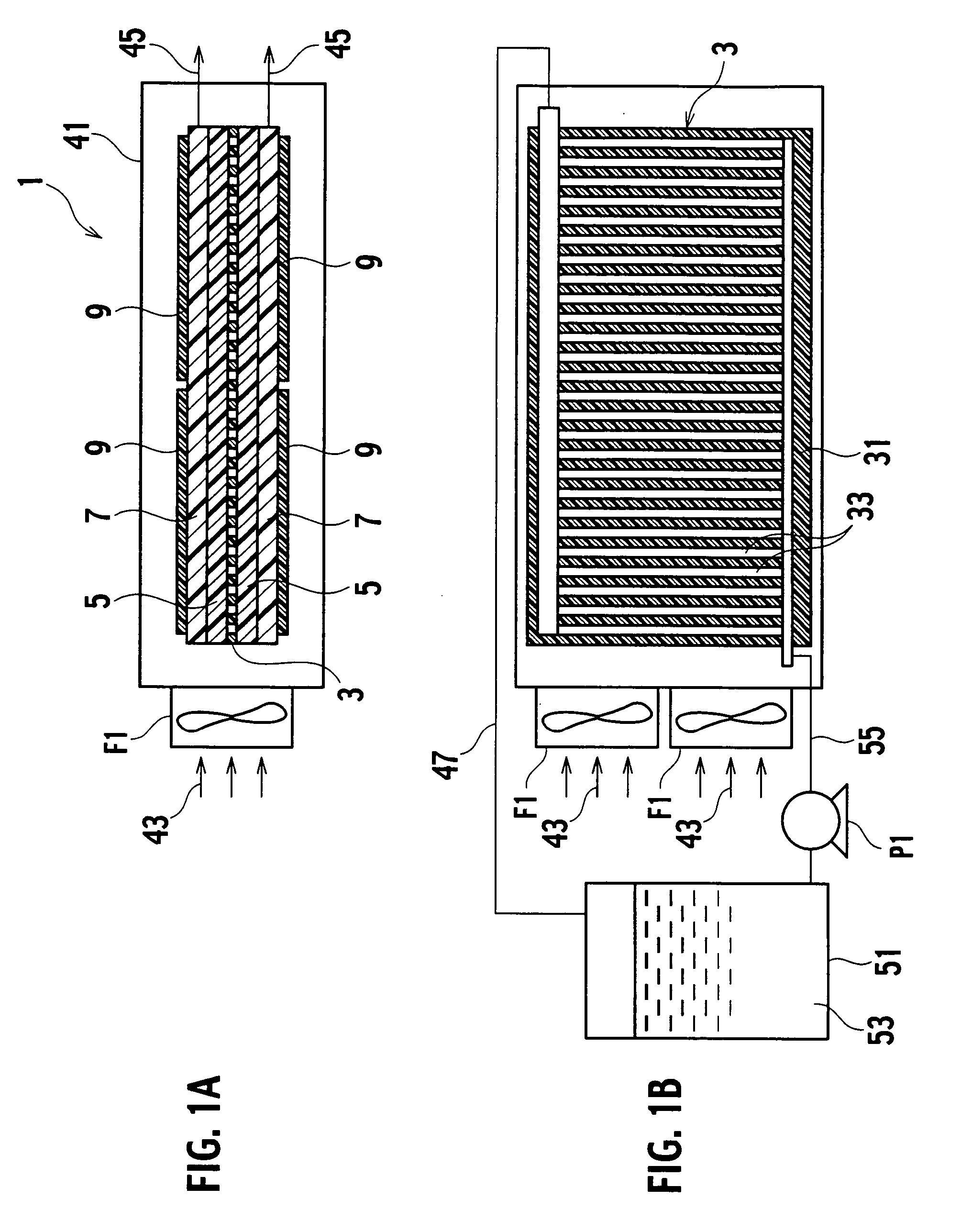
[0023] A fuel cell in accordance with the first embodiment of the present invention is, as shown in FIG. 1A, provided with a fuel distribution layer 3, a back-diffusion barrier layer 5 layered on the fuel distribution layer 3, an anode flow path 7 further layered on the back-diffusion barrier layer 5, and a membrane electrode assembly 9 layered on the anode flow path 7. FIG. 1A illustrates an example in which layers are one on one layered on both faces of the fuel distribution layer 3, but may be layered only on one of the faces.
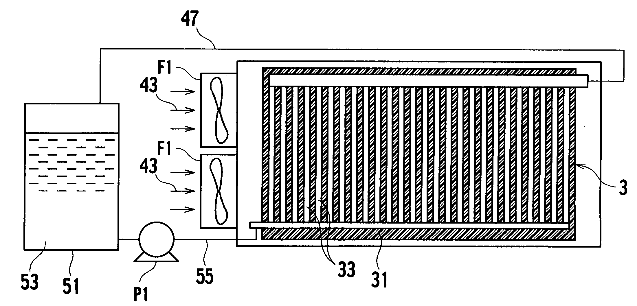
[0024] The fuel distribution layer 3 is, as shown in FIG. 1B, provided with a distribution body 31 and a fuel distribution path 33 branched into plural ways to pass through the substantially whole face of the distribution body 31.
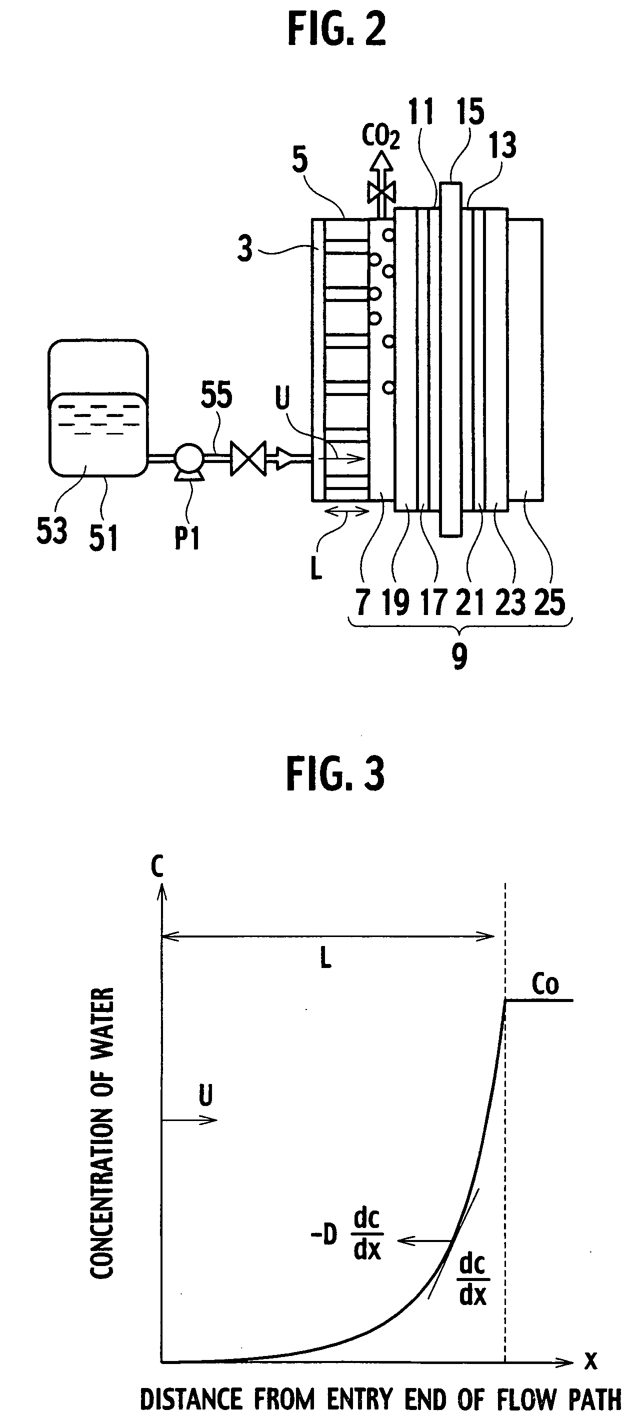
[0025] The back-diffusion barrier layer 5 is a thin plate-like layer made of carbon for example, which has a number of micro pores pene...
second embodiment
[0044] Next, the present invention will be described hereinafter with reference to FIG. 4. In the following description, substantially the same elements as any of the aforementioned elements are referenced with the same numerals and the detailed descriptions are omitted.
[0045] In a fuel cell 101 in accordance with the second embodiment, the membrane electrode assembly 9 is directly layered on the fuel distribution layer 3. Moreover, instead of the fuel tank 51, a mixing tank 61 is linked with the fuel supply path 55 and the recovery path 47. A fuel tank 65 is linked with the mixing tank 61 via a fuel replenishment path 69 in which a pump 61 intervenes. The fuel tank 65 contains methanol aqueous solution 67 containing 25M (namely, pure) or less and 10M or more methanol and a proper water content as the fuel. The mixing tank 61 contains methanol aqueous solution 63 having a concentration proper for a power generation, such as a concentration of 3M.
[0046] When operating the pump P1, t...
third embodiment
[0050] Next, the present invention will be described hereinafter with reference to FIG. 5. In the following description, substantially the same elements as any of the aforementioned elements are referenced with the same numerals and the detailed description are omitted.
[0051] In the present embodiment, the fuel distribution layer 3 and the back-diffusion barrier layer 5 are omitted and the fuel supply path 55 is spatially separated from the anode flow path 7. The fuel supply path 55 is further provided with a throttle valve 57 to discharge the fuel as droplets from an end thereof with regulating a flow rate of the fuel. The spatial relation between the end of the fuel supply path 55 and the anode flow path 7 is such that the droplets are capable of directly reaching the anode flow path 7. Because the fuel supply path 55 is not directly connected to the anode flow path 7, water is incapable of back-diffusion toward a direction opposed to the supply of the fuel. Thereby the back-diffu...
PUM
 Abstract
Description
Claims
Application Information