Method of manufacturing orientation film and method of manufacturing liquid discharge head

a technology of orientation film and liquid discharge head, which is applied in the direction of printing, electrical equipment, and electromechanical/electrostrictive/magnetostrictive devices, etc., can solve the problems of poor controllability, complex manufacturing process, and inability to generally use solid phase growth, etc., to achieve simple process, wide range of substrate material choices, and high quality

Inactive Publication Date: 2006-10-05
FUJIFILM HLDG CORP +1
View PDF6 Cites 13 Cited by
  • Summary
  • Abstract
  • Description
  • Claims
  • Application Information

AI Technical Summary

Benefits of technology

[0020] According to the present invention, the film in uniform, strong, and close contact with the seed substrate can be formed by performing film formation using the aerosol deposition method, and the solid phase growth can progress uniformly and efficiently from the seed substrate side in the subsequent heat treatment. Therefore, high quality orientation films can be manufactured in the simple process. Further, since the crystal can be oriented even at relatively low heat treatment temperature, the range of choices of substrate materials can be expanded. Therefore, industrial ceramic film orienting process can be realized at low cost by using inexpensive materials such as silicon. Furthermore, since the property of a functional material such as a piezoelectric material film can be improved by using such a method of manufacturing an orientation film, the performance of the liquid discharge head using a piezoelectric actuator including the piezoelectric material film as driving means can be improved and the cost of manufacturing the liquid discharge head can be reduced.

Problems solved by technology

Solid phase growth is not generally used because of slow growth rate, poor controllability and so on.
The first problem is that the polycrystalline ceramic material and the single crystal material are located in contact with each other.
However, such a step is added, the entire manufacturing process becomes complex and the apparatuses and equipment become complicated.
Further, in the case where the area of the orientation film is increased, it is very difficult to uniformize the surfaces of the polycrystalline ceramic material and the single crystal material.
The second problem is that the ceramic sintered compact is used as a target to be oriented (polycrystalline ceramic material).
However, in this case, it is necessary to produce grain growth by heating the pressed compact afterwards.
That is, the particle diameter has already been large at the time of fabrication of a ceramic sintered compact, and therefore, considerable energy is required to promote the solid phase growth from the condition.
The third problem is that the direction of orientation is controlled by temperature gradient.
However, it is difficult to precisely control the temperature gradient, and the control of the temperature gradient is virtually impossible in the case where a film having a thickness of ten to several hundreds of micrometers is oriented.
The fourth problem is that the single crystal substrate is used as the starting point of solid phase growth.
This is because the single crystal substrate is generally expensive and often restricted in area.
Accordingly, the problem is a major issue in cost and technology when the device is put into practical use.

Method used


Image

  • Method of manufacturing orientation film and method of manufacturing liquid discharge head
  • Method of manufacturing orientation film and method of manufacturing liquid discharge head
  • Method of manufacturing orientation film and method of manufacturing liquid discharge head

Examples


first embodiment

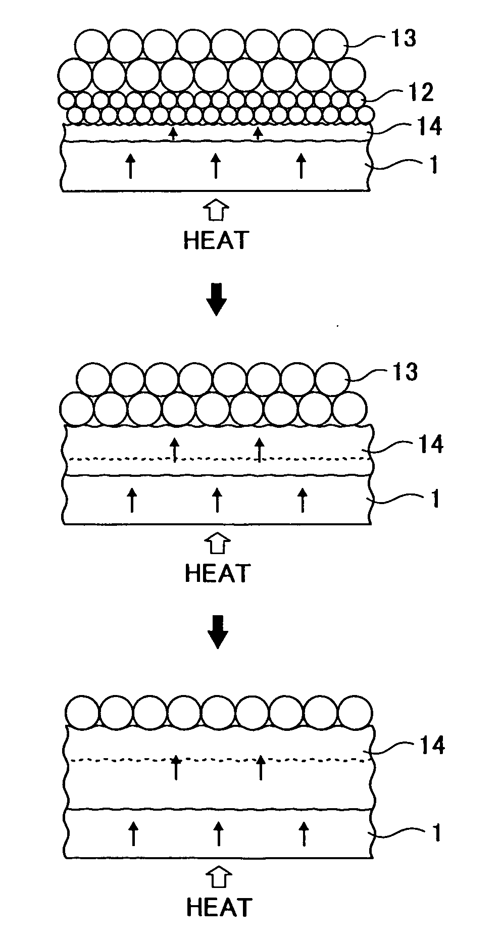
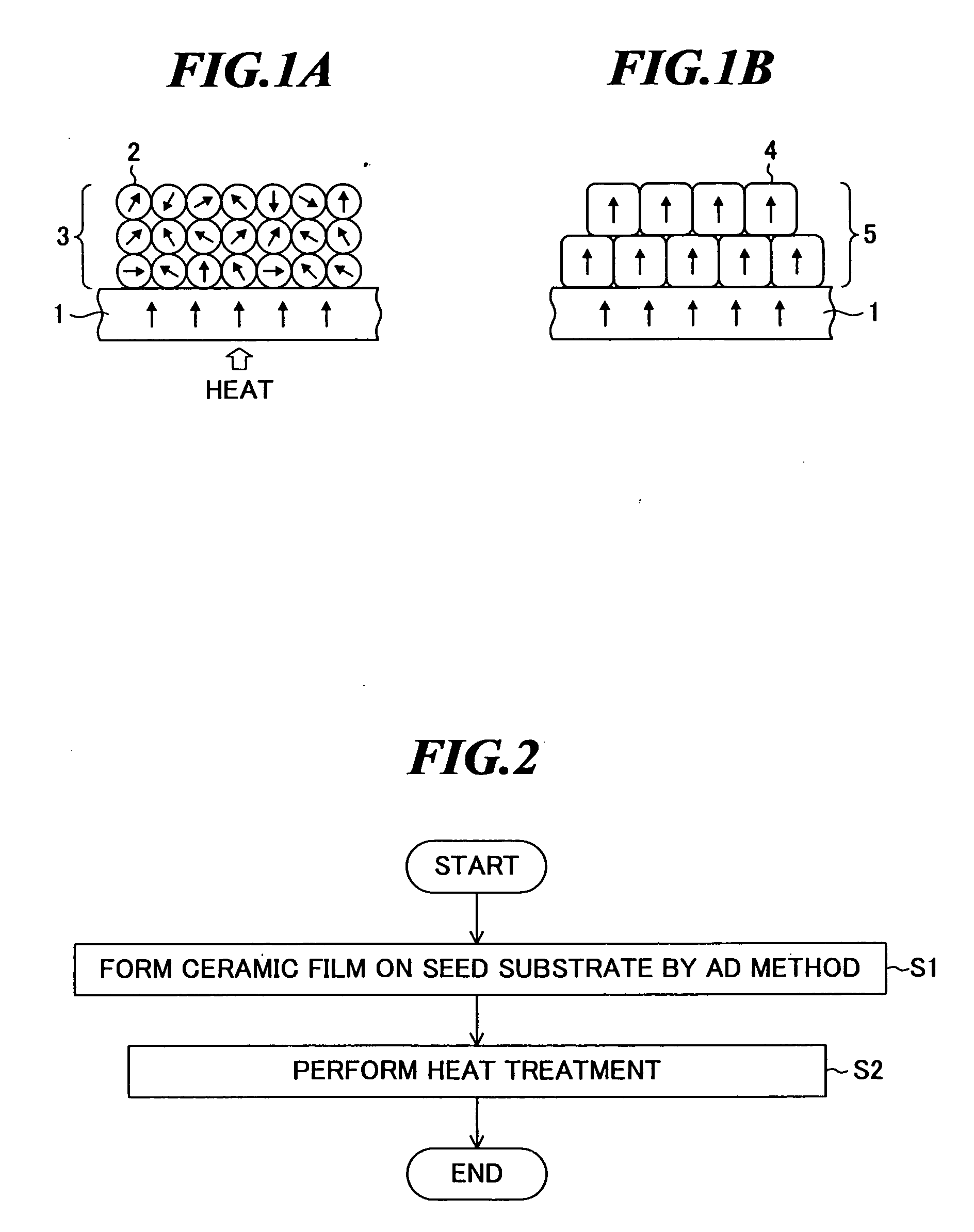
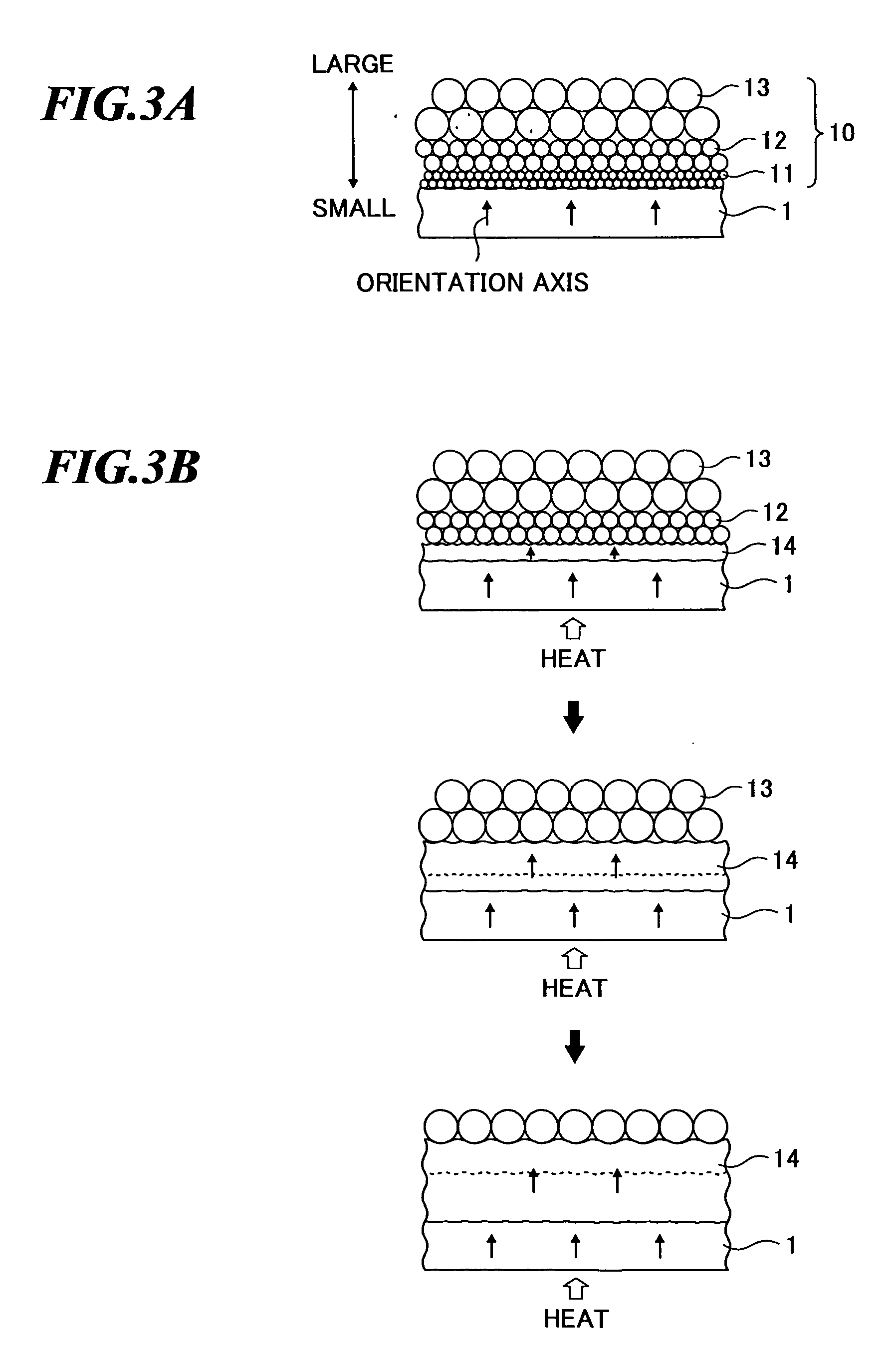
[0039]FIG. 2 is a flowchart showing the method of manufacturing an orientation film according to the present invention. Further, FIGS. 3A and 3B are diagrams for explanation of the method of manufacturing an orientation film according to the embodiment.

[0040] First, at step S1 in FIG. 2, a ceramic film 10 having a predetermined particle diameter distribution is formed on the seed substrate 1 as shown in FIG. 3A. In this regard, the film formation is performed by using an aerosol deposition (AD) method, which will be described later.

[0041] As the seed substrate 1, a single crystal substrate of magnesium oxide (MgO), SRO (SrRuO: strontium ruthenium oxide), etc., or a polycrystal substrate in which crystal grains are oriented to some degree is used.

[0042] In the embodiment, the ceramic particles 11 to 13 contained in the ceramic film 10 are distributed such that the diameter changes along the thickness direction. That is, the particle diameter gradually increases from the layer (lowe...

second embodiment

[0072] Next, the method of manufacturing an orientation film according to the present invention will be explained by referring to FIGS. 5A to 7. In the embodiment, a solid solution impurity having a function of suppressing crystal grain growth is used as an additive.

[0073] First, at step S1 in FIG. 2, a ceramic film 20 to which the solid solution impurity has been added is formed on the seed substrate 1 as shown in FIG. 5A. In the ceramic film 20, solid solution impurities 22 located between ceramic particles 21 are distributed such that the concentration gradually becomes higher from the layer (lower layer) near the seed substrate 1 toward the upper layer. Further, as the solid solution impurity, MgO, Al2O3 or the like is used.

[0074] Such a ceramic film 20 can be formed by a film forming apparatus as shown in FIG. 6 or 7 using the AD method.

[0075] The film forming apparatus shown in FIG. 6 is additionally provided with an additive supply part 110 and an additive supply nozzle 111...

third embodiment

[0088] Next, the method of manufacturing an orientation film according to the present invention will be described by referring to FIGS. 2, 8A, and 8B. In the embodiment, a sintering auxiliary agent (low melting point auxiliary agent) that promotes crystal grain growth is used as an additive.

[0089] First, at step S1 in FIG. 2, a ceramic film 30 to which the sintering auxiliary agent has been added is formed on the seed substrate 1 as shown in FIG. 8A. In the ceramic film 30, sintering auxiliary agents 32 located between ceramic particles 31 are distributed such that the concentration gradually becomes higher from the layer (lower layer) near the seed substrate 1 toward the upper layer. As the sintering auxiliary agent, for example, PbO, LiBiO2, LiF, Li3PO4, LI2CO3, Li2SO4, Li2O3, Bi2O3, Li2CO3—Bi2O3—B2O3, BiF3—LiF, PbO—B2O3, PbF2—PbBr2, ZrF4—LiF, PbO—Bi2O3—V2O5, Pb complex compound or Bi complex compound is used singly or the mixture of them is used.

[0090] Such a ceramic film 30 is ...


PUM

PropertyMeasurementUnit
diameteraaaaaaaaaa
sizeaaaaaaaaaa
sizeaaaaaaaaaa

Abstract

A method of manufacturing an orientation film which method is suitable for manufacturing an orientation film containing a ceramic at low cost. The method includes the steps of: (a) forming a ceramic film on a seed substrate in which crystal orientation is controlled at least on a surface thereof by using an aerosol deposition method of injecting powder toward a substrate and depositing the powder on the substrate; and (b) heat-treating the ceramic film formed at step (a) to form an orientation film in which crystal grains contained in the ceramic film is oriented.

Description

BACKGROUND OF THE INVENTION [0001] 1. Field of the Invention [0002] The present invention generally relates to a method of manufacturing an orientation film, and specifically to a method of manufacturing a ceramic orientation film containing a piezoelectric ceramic. Furthermore, the present invention relates to a method of manufacturing a liquid discharge head (injection head) utilizing such a method of manufacturing an orientation film. [0003] 2. Description of a Related Art [0004] A structure in which electrodes are formed on both sides of a piezoelectric material is utilized in various applications such as a piezoelectric actuator, a piezoelectric pump, an ink head of an inkjet printer and an ultrasonic transducer. In recent years, with the developments of MEMS (micro electro mechanical systems) related devices, elements having such structures have been microfabricated still further and packaged more densely. Accordingly, microfabrication and improvement in performance are desire...

Claims


Application Information

Patent Timeline
Patent Type & Authority Applications(United States)
IPC IPC(8): H01L21/84
CPCB41J2/161B41J2/1623B41J2/1628B41J2/1629B41J2/1632Y10T29/49401B41J2/1646H01L41/314Y10T29/49155Y10T29/42B41J2/1643H10N30/074
Inventor NIHEI, YASUKAZU
Owner FUJIFILM HLDG CORP
Why Eureka
Try Eureka