
Catheter system for the treatment of atrial fibrillation

a catheter system and atrial fibrillation technology, applied in medical science, surgical instruments for cooling, surgery, etc., can solve the problems of not always providing a clear answer and a large amount of procedure time, and achieve the effect of reducing the risk of iatrogenic pulmonary vein stenosis, rapid and accurate positioning of the toroidal balloon, and reducing the risk of pulmonary vein stenosis

Inactive Publication Date: 2006-10-05
FISCHELL ROBERT E +1
View PDF3 Cites 154 Cited by
  • Summary
  • Abstract
  • Description
  • Claims
  • Application Information

AI Technical Summary

Benefits of technology

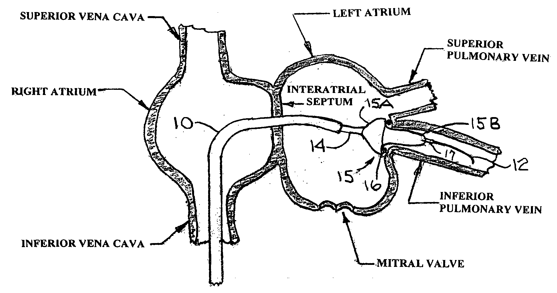
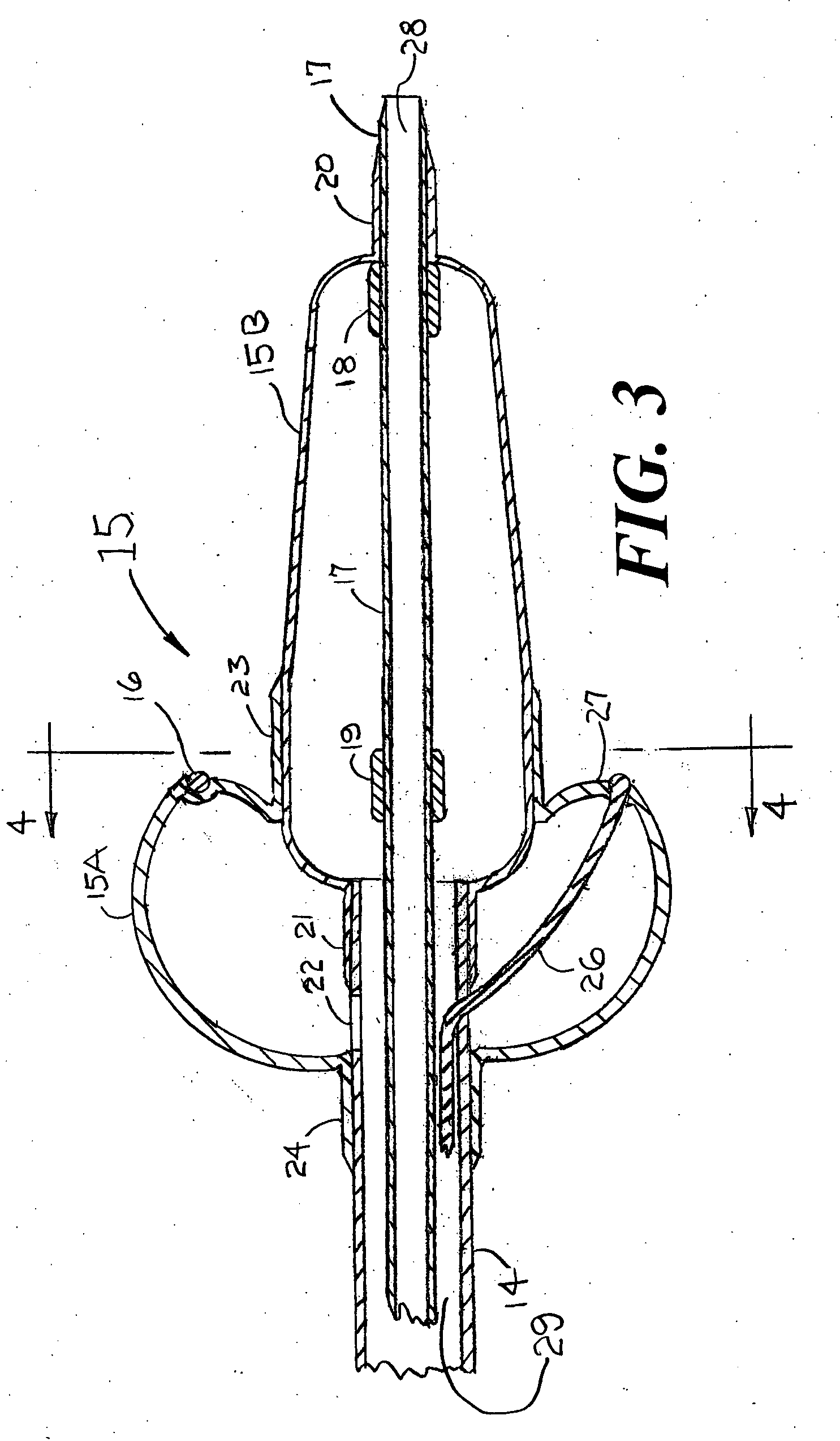
[0004] The present invention is designed to overcome the shortcomings of prior art methods and devices for the treatment of atrial fibrillation. Explicitly, the present invention is a catheter means and a method for rapidly and accurately positioning a toroidal balloon with its distal surface placed tightly against the endocardial surface of the left atrium at a location that is close to the ostium of a pulmonary vein. On the exterior surface of the toroidal balloon can be an electrically conducting wire that is capable of causing rf energy to be placed into the tissue of the left atrium so as to ablate that tissue to alter the conduction of aberrant electrical signals of the heart that are associated with atrial fibrillation. The toroidal balloon is actually wrapped circumferentially around a tapered balloon whose proximal diameter is just slightly less than or equal to the diameter near the ostium of the pulmonary vein into which the tapered balloon is inserted. The positions of the tapered balloon and its surrounding toroidal balloon are such that the ablation of the tissue of the left atrium occurs at a diameter that is approximately 1-4 mm greater than the diameter of the ostium of the pulmonary vein into which the tapered balloon is inserted. In this manner, only the tissue of the left atrium, surrounding the ostium of the pulmonary vein is ablated. Thus, injury to the pulmonary vein can be minimized in order to reduce the risk of iatrogenic pulmonary vein stenosis. This system can be applied successively to at least one or as many as all four of the pulmonary veins that enter the left atrium. The same type of catheter system can be used to ablate the endocardial surface of the right atrium centered around the ostium of the superior vena cava.
[0010] 5) appropriate anticoagulation is given to minimize the risk of left atrial thrombus during the rest of the manipulations,
[0026] Visualization of the left and right atria and pulmonary veins is best accomplished by intracardial or esophageal ultrasound as is presently done in the treatment of atrial fibrillation. Fluoroscopy may also be utilized for improving the visualization of the left atrium and pulmonary veins. The optimal guiding catheter and / or guide wire to be used for such a procedure would be of the steerable type that is now well known in the field of interventional cardiology. By utilizing steerable equipment, placement of the guide wire and balloon catheter into each pulmonary vein could be accomplished more expeditiously. The guide wire used would typically have a diameter of 0.035 or 0.038 inches. The guiding catheter used for the procedure would typically have a diameter between 8 FR and 14 FR.
[0027] Thus one object of the present invention is to create a lesion of the tissue of the left atrium that is in close proximity to the ostium of at least one pulmonary vein thereby preventing the occurrence of atrial fibrillation, the procedure being performed by means of a percutaneously inserted catheter system.

Problems solved by technology

Unfortunately, mapping takes a great deal of procedure time and does not always provide a clear answer as to the region of the heart that must be ablated in order to stop the episodes of atrial fibrillation being experienced by the patient.

Method used


Image

  • Catheter system for the treatment of atrial fibrillation
  • Catheter system for the treatment of atrial fibrillation
  • Catheter system for the treatment of atrial fibrillation

Examples


Embodiment Construction

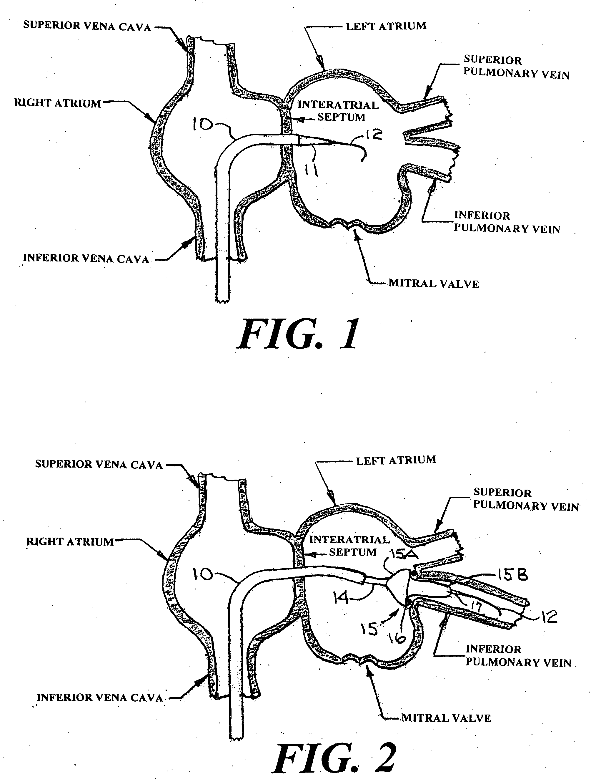
[0036]FIG. 1 is a cross section of the right and left atria of a human heart showing two of the four pulmonary veins that enter the left atrium. FIG. 1 does not attempt to accurately display the exact location of these two pulmonary veins. It should be understood that there are actually four pulmonary veins that enter the left atrium. FIG. 1 also shows a distal portion of a guiding catheter 10 that is designed explicitly for introduction through the left or right femoral vein; from there through the inferior vena cava, and from there into the right atrium. After the trans-septal placement of a guide wire 12 into the left atrium, the dilator 11 and the distal end of the guiding catheter 10 can be advanced over the guide wire 12 and through the interatrial septum into the left atrium. The dilator 11 can include a radiopaque metal marker ring (not shown) at or near its distal end to improve the visualization of the dilator 11 by means of fluoroscopy or echocardiography. After the dista...


PUM


Abstract

Disclosed are a means and method for rapidly and accurately positioning a toroidal balloon with its distal surface placed tightly against the endocardial surface of the left atrium at a location that is close to the ostium of a pulmonary vein. On the exterior surface of the toroidal balloon can be an electrically conducting wire that is capable of causing rf energy to be placed into the tissue of the left atrium so as to ablate that tissue to alter the conduction of aberrant electrical signals of the heart that are associated with atrial fibrillation. The toroidal balloon is wrapped circumferentially around a tapered balloon that is placed into the pulmonary vein. This system can be applied successively to at least one or as many as all four of the pulmonary veins that enter the left atrium to treat the patient's atrial fibrillation.

Description

FIELD OF USE [0001] This invention is in the field of methods and devices for the treatment of atrial fibrillation. BACKGROUND OF THE INVENTION [0002] Atrial fibrillation is a disorder of the heart that (in the year 2005) affects more than 2 million Americans and a comparable number of patients outside the USA. There have been many treatments for this disorder including surgery and percutaneous catheter treatments that require mapping of the electrical signals within the heart and then ablative destruction of the region of the pulmonary vein that is in close proximity to the left atrium. The mapping procedure is often very difficult and time consuming, thus significantly extending the time required for the procedure. The surgical operation requires considerable skill and a great deal of time for that procedure. Furthermore, the recovery time from the surgical treatment is significantly greater than the recovery time from a percutaneous catheter procedure for the treatment of this di...

Claims


Application Information

Patent Timeline
Patent Type & Authority Applications(United States)
IPC IPC(8): A61B18/14
CPCA61B18/02A61B18/1492A61B2018/00214A61B2018/046A61B2018/00375A61B2018/0212A61B2018/0022A61B2018/00232
Inventor FISCHELL, ROBERT E.FISCHELL, TIM A.
Owner FISCHELL ROBERT E
Learn More