Liquid tank and fuel cell system with fuel monitoring
a fuel cell and liquid tank technology, applied in the field of liquid tank and fuel cell system, can solve the problems of fuel consumption and the need for complex measures in the dmfc system to detect empty fuel, and achieve the effect of easy monitoring
- Summary
- Abstract
- Description
- Claims
- Application Information
AI Technical Summary
Benefits of technology
Problems solved by technology
Method used
Image
Examples
example 1
[0054] A detailed description of the structure of a methanol tank 120 according to a first example of carrying out the embodiment of the present invention will now be given, with reference to FIGS. 5 and 6. FIG. 5 is a perspective view showing the appearance of the methanol tank 120. FIG. 6 is a perspective view schematically showing the internal structure of the methanol tank 120.
[0055] As shown in FIG. 5, a remaining indicator window 124 is provided at a side 123a which is a line of intersection between an upper surface 122a and a lateral surface 122b of the methanol tank 120. The remaining indicator window 124 provides a means to visually alert a user that the remaining quantity of highly-concentrated methanol water solution or pure methanol in the methanol tank 120 is relatively small. The remaining indicator window 124 may be provided at a side 123b where the lateral surface 122b and a back surface 122c intersect or a side 123c where the back surface 122c and the flat surface ...
example 2
[0058] A detailed description of the structure of a methanol tank 220 according to a second example of carrying out the embodiment of the present invention will now be given, with reference to FIGS. 7 and 8. FIG. 7 is a perspective view showing the appearance the methanol tank 220. FIG. 8 is a perspective view schematically showing the internal structure of the methanol tank 220.
[0059] As shown in FIG. 7, a remaining indicator window 224 is provided to extend from a side 223a to an upper surface 222a of the methanol tank 220, the side 223a being a line of intersection between the upper surface 222a and a lateral surface 222b of the methanol tank 220. The remaining indicator window 224 provides a means to visually alert a user that the remaining quantity of highly-concentrated methanol water solution or pure methanol in the methanol tank 220 is relatively small.
[0060] As shown in FIG. 7, the methanol tank 220 accommodates a pack 221 which is of practically the same dimensions as th...
first specific embodiment
for Improvement of Viewability of Fuel Remaining Quantity
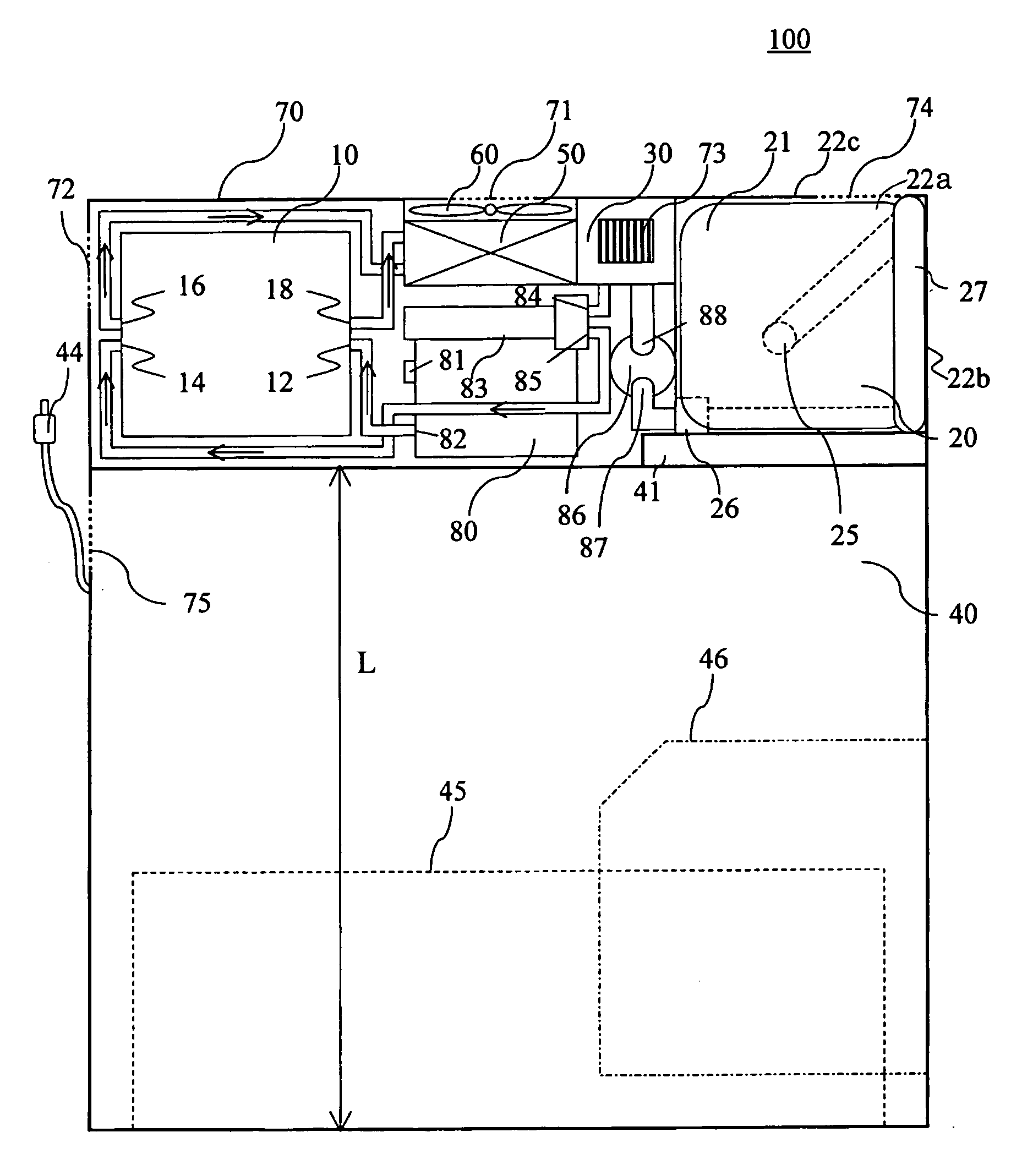
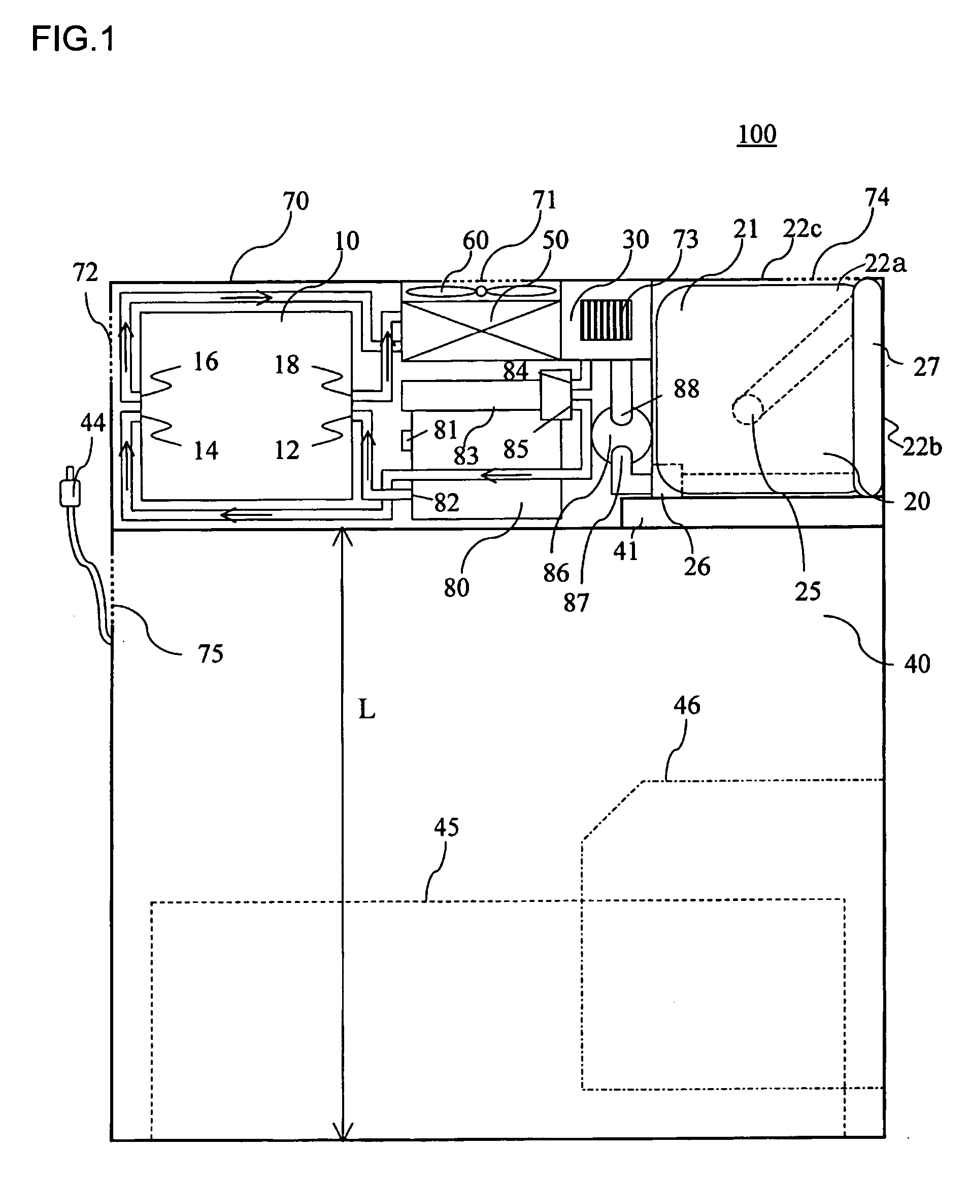
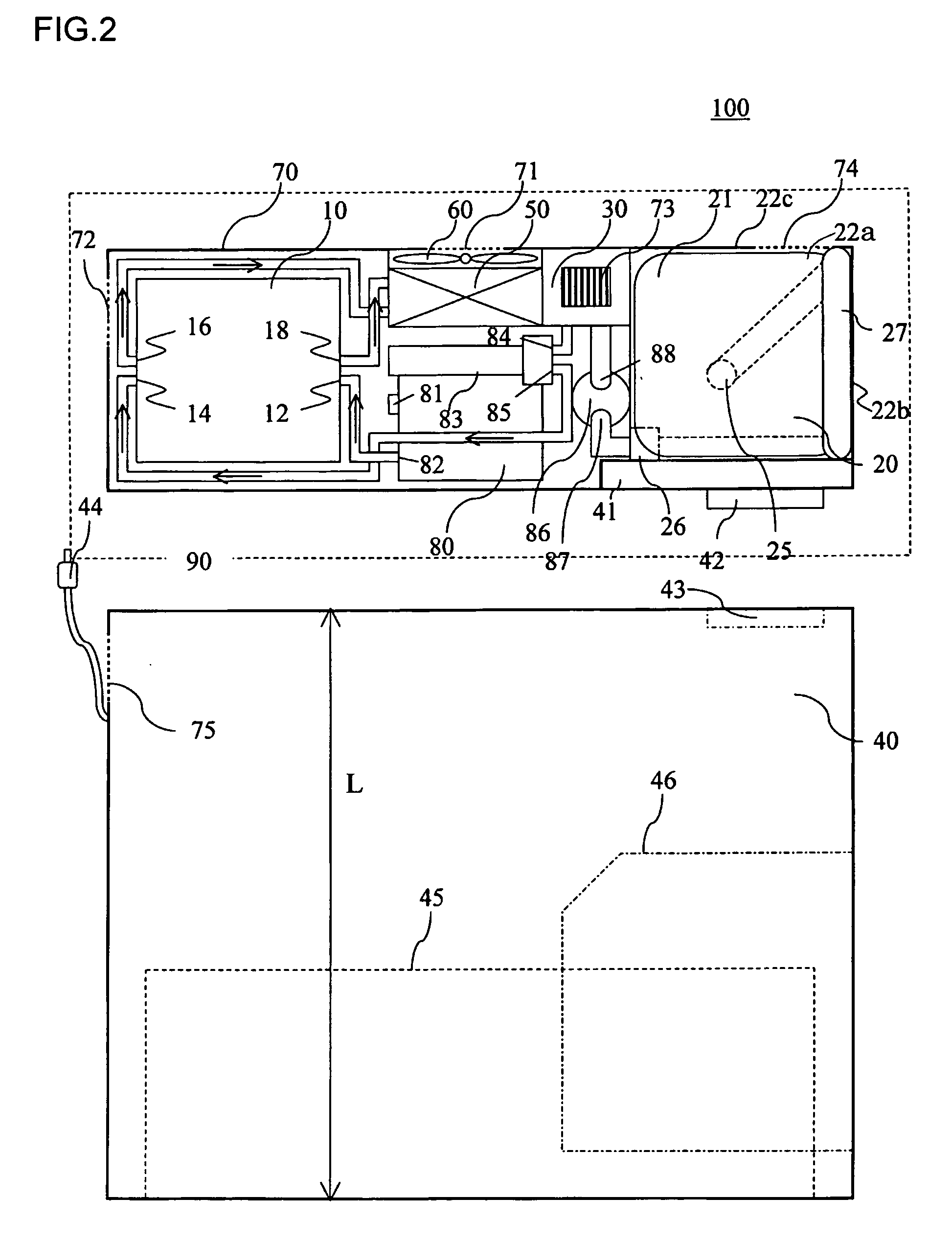
[0063]FIG. 9 is cross sectional view of essential parts taken along the line 9-9 of FIG. 5. The outlet pipe 127 is viewable through the remaining indicator window 124 made of transparent resin or the like.
[0064] The outlet pipe 127 has a tubular or cylindrical structure. Alternatively, the cross section of the pipe may be elliptical. It is preferable that the outlet pipe 127 have a predetermined refractive index as well as having transparency, resistance to chemicals and water repellency. In this respect, the outlet pipe 127 is preferably made of a material such as silicon rubber, fluoropolymer resin or fluororubber. It is preferable that the refractive index of the outlet pipe 127 be approximately 1.0. The refractive index within the range of +10% of the refractive index of liquid flowing through the outlet pipe 127 is tolerable. If the outlet pipe 127 is thin, refraction in the outlet pipe 127 less affects viewability. Pref...
PUM
| Property | Measurement | Unit |
|---|---|---|
| operating temperature | aaaaa | aaaaa |
| temperature | aaaaa | aaaaa |
| temperature | aaaaa | aaaaa |
Abstract
Description
Claims
Application Information
 - R&D
- Intellectual Property
- Life Sciences
- Materials
- Tech Scout
- Unparalleled Data Quality
- Higher Quality Content
- 60% Fewer Hallucinations
Browse by: Latest US Patents, China's latest patents, Technical Efficacy Thesaurus, Application Domain, Technology Topic, Popular Technical Reports.
© 2025 PatSnap. All rights reserved.Legal|Privacy policy|Modern Slavery Act Transparency Statement|Sitemap|About US| Contact US: help@patsnap.com


