
Adhesive-assembled fiber-optic interferometer

a fiber-optic interferometer and fiber-optic technology, applied in the field of fiber-optic sensors, can solve the problems of fiber breakage, retain the disadvantage of having the sensor sensitivity strictly defined by the cavity length, and it is difficult, if not impossible, to properly control the ingress of adhesive into the capillary. , to achieve the effect of accurately controlling the amount of adhesive swelling and slowly complete the curing of adhesiv

Inactive Publication Date: 2006-10-19
OPSENS
View PDF25 Cites 17 Cited by
  • Summary
  • Abstract
  • Description
  • Claims
  • Application Information

AI Technical Summary

Benefits of technology

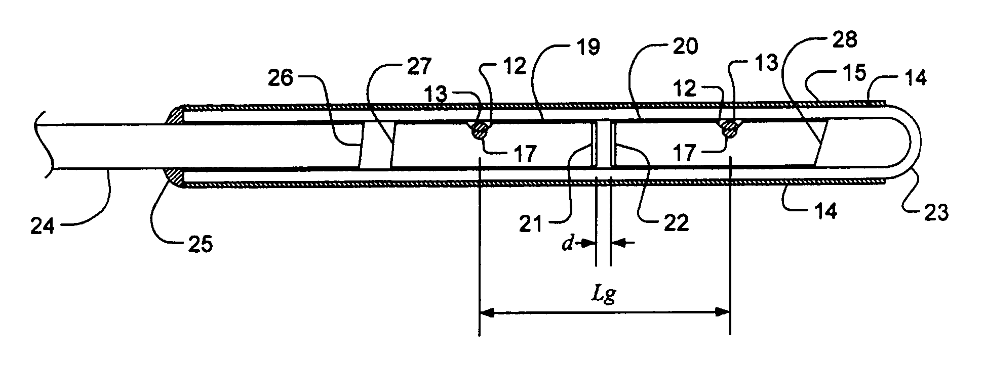
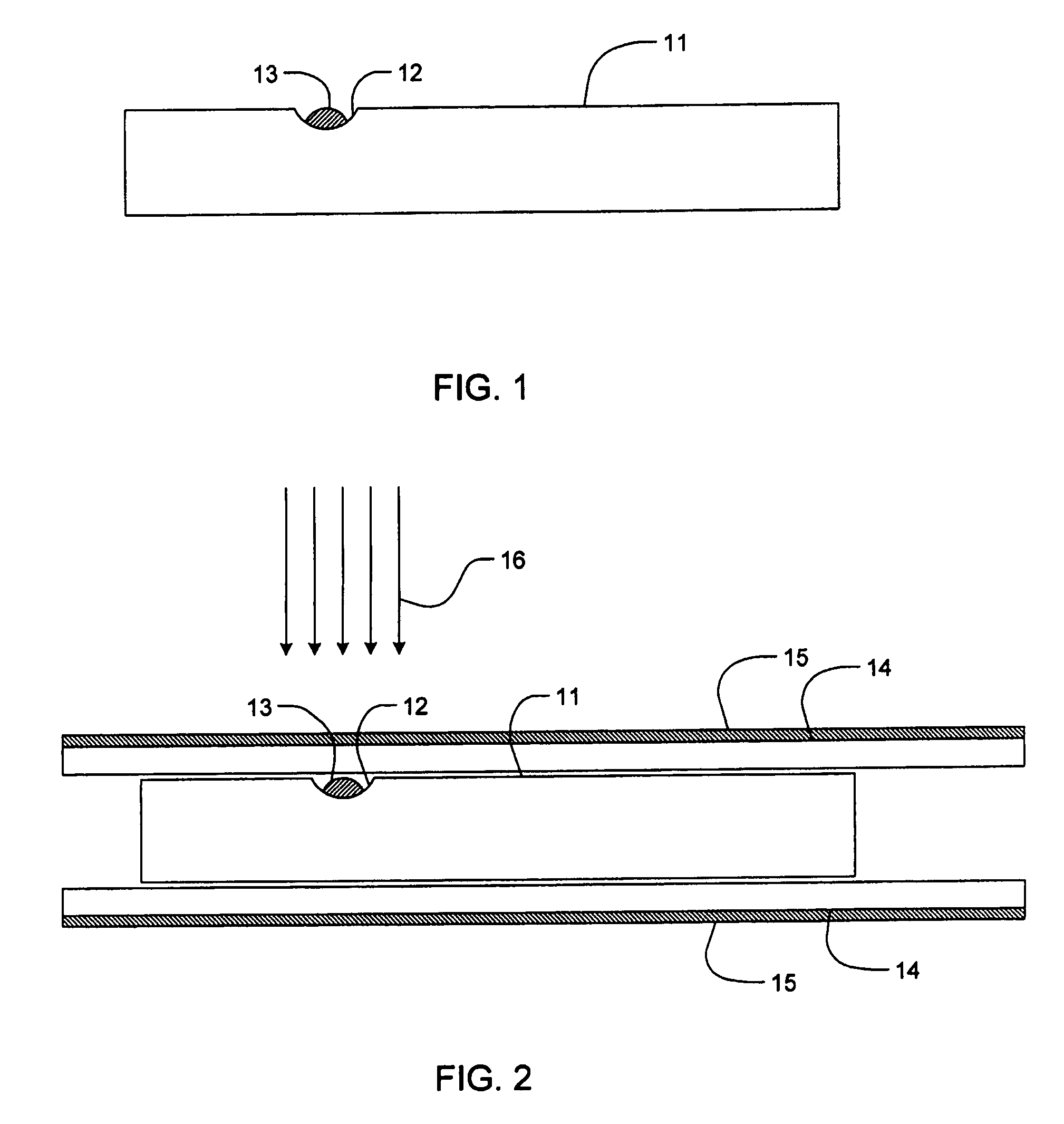
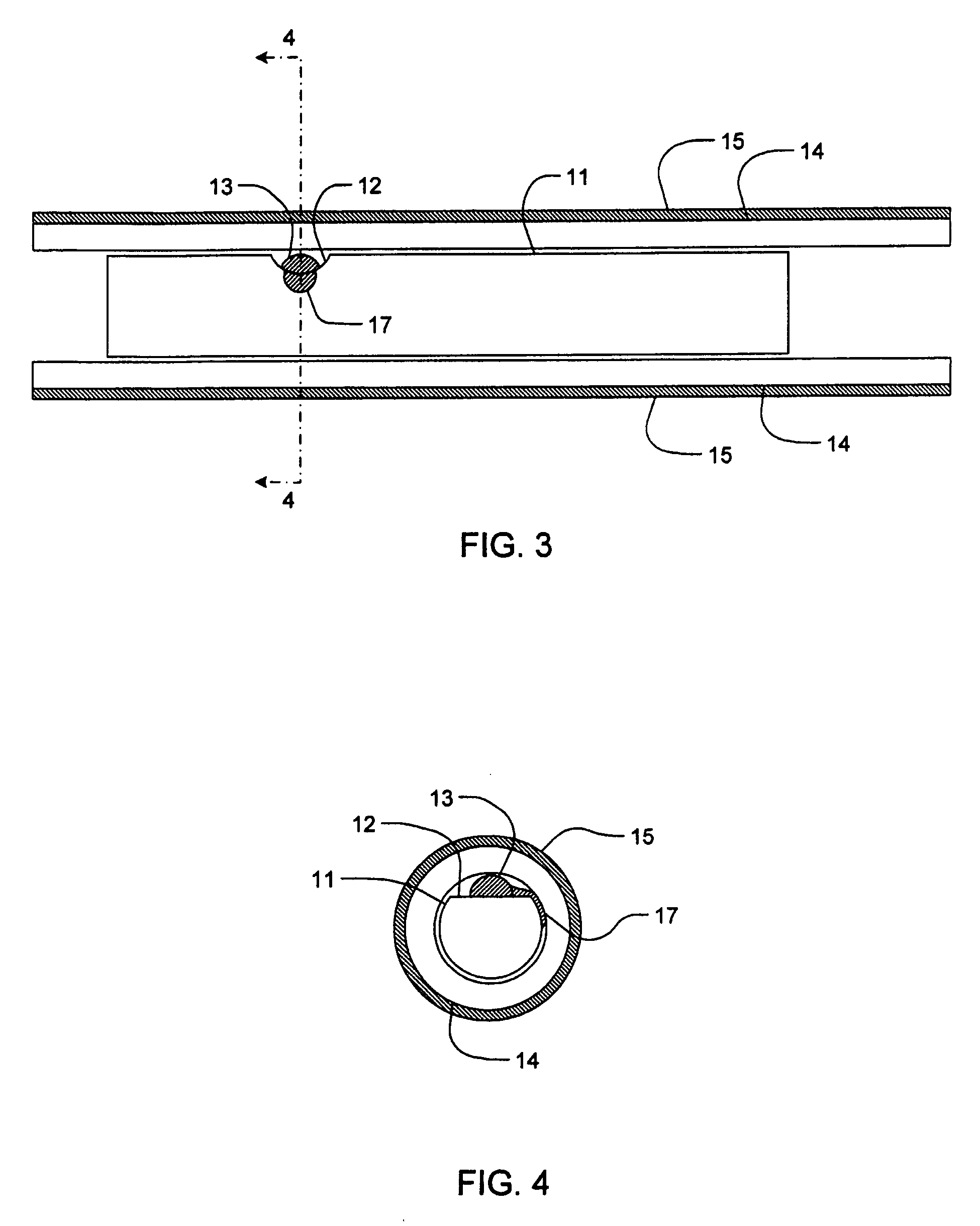
[0014] The invention provides a recess on the side of the fiber. The recess acts as a container or reservoir for the adhesive. At room temperature, the hardened or partially cured adhesive is solid. Hence, the recess makes room for the adhesive bead to enter the capillary along with the fiber. Once inside the capillary, heating the assembly will make the adhesive to become liquid, expand and swell out of the recess. If one can heat and cool rapidly on demand, the amount of adhesive swelling can be accurately controlled. Once a suitable bond area has been attained, it is possible, if necessary, to slowly complete the curing of the adhesive by an automatic temperature-controlled oven without inducing further swelling of the adhesive.

Problems solved by technology

Second, since the light is guided by the optical fiber between the mirrors, transverse strain can affect the reading by inducing birefringence and refractive index changes.
This configuration has the same drawbacks as the Bragg mirrors added to the fact that the fusion splices, because of the presence of the mirrors, compromise the fiber integrity, which can lead to fiber breakage when the sensor is exposed to high strains.
It eliminates the transverse strain problems encountered on the two previous configurations but it retains the disadvantage of having the sensor sensitivity strictly defined by the cavity length.
However, it is very difficult, if not impossible, to properly control the adhesive ingression into the capillary.
Hence, the sensitivity factor of the sensor is hard to determine because of the non-uniform glue line inside the capillary.
This can also lead to non-linearity in the sensor response: because the adhesive is a relatively soft material, the effective position of the glue line is moving as stress is applied to the sensor.
However, this is done at the cost of added fragility since the protective polyimide buffer of the capillary is burned over the solder points and also because of the residual stress induced by the welding process.
Up to now, it has not been feasible to do this in a systematic, reproducible manner.

Method used


Image

  • Adhesive-assembled fiber-optic interferometer
  • Adhesive-assembled fiber-optic interferometer
  • Adhesive-assembled fiber-optic interferometer

Examples


Embodiment Construction

[0028] In the following description of the embodiments, references to the accompanying drawings are by way of illustration of an example by which the invention may be practiced. It will be understood that other embodiments may be made without departing from the scope of the invention disclosed.

[0029] Referring to FIG. 1, a small recess 12, or a notch, has been carved on the side of an optical fiber 11. The fiber diameter is typically 125 μm. Hence the recess is very small: typically 30 μm deep and 50 μm wide. Many techniques can be used to make this recess: laser ablation, chemical etching and others. But one of the simplest ways is using a dicing saw with a thin diamond blade. If the blade has been properly worn out, the blade's edge forms a small radius. So when cutting in the direction perpendicular to the axis of the fiber, one can obtain a shallow cylindrical cut on the fiber surface. Good results have been obtained with a 55 mm diameter, 100 μm thick resin blade with 46 μm pa...


PUM


Abstract

A method to assemble optical fiber devices and a fiber optic sensor is provided. It features a small adhesive joint between the fiber and a capillary tube by means of a small recess carved on the side of the fiber. This recess acts as a reservoir for the adhesive during the insertion of the fiber inside the tube. Then, the tube is heated so that the adhesive swells out of the recess to make the joint between the tube and the fiber. This method is used to assemble a fiber optic Fabry-Perot interferometer. This interferometer can be used as a sensor for the measurement of a number of physical parameters.

Description

CROSS-REFERENCE TO RELATED APPLICATIONS [0001] This application claims priority under 35USC§119(e) of U.S. provisional patent application 60 / 664,648, filed Mar. 24, 2005, the specification of which is hereby incorporated by reference.FIELD OF THE INVENTION [0002] The present invention generally relates to the field fiber-optic devices, and more specifically to fiber optic sensors wherein a fiber-optic interferometer is used for measuring a physical parameter such as a pressure, temperature, etc., and especially strain of a deformed body. The methods introduced by this invention can also be used in other fields such as optical telecommunication devices and optical instrumentation. BACKGROUND OF THE ART [0003] Strain sensors using fiber-optic Fabry-Perot interferometers (FFPI) are now of common use where a harsh environment or high electric field or noise prevents the use of conventional foil electric strain gages. FFPI can also be made very small, thus enabling its use in locations u...

Claims


Application Information

Patent Timeline
IPC IPC(8): G02B6/00
CPCG01J3/1895G01J3/26G01B2290/25G01B11/161G01B11/18G01D5/268G01D5/35312
Inventor VAN NESTE, RICHARDBELLEVILLE, CLAUDEBELLEVILLE, NINONBUSSIERE, SYLVAIN
Owner OPSENS
Learn More