Tidal vertical flow wastewater treatment system and method

a wastewater treatment system and vertical flow technology, applied in water cleaning, filtration separation, separation processes, etc., can solve the problems of inability to achieve advanced treatment, large land footprint, poor denitrification performance of tide flow systems, etc., to achieve advanced simultaneous nitrification and denitrification, reduce the treatment footprint, and reduce the effect of energy consumption

Inactive Publication Date: 2006-10-26
IASIS USA LC +1
View PDF91 Cites 7 Cited by
  • Summary
  • Abstract
  • Description
  • Claims
  • Application Information

AI Technical Summary

Benefits of technology

[0016] The process design in various embodiments integrates wetland and lagoon treatment technology in an inventive way that represents an improvement over the existing state of the art in lagoon, wetland, and combined lagoon / wetland wastewater treatment systems. The process design of the present invention also includes elements of environmental and ecological engineering design that significantly improve the state of the art of wastewater treatment in general, and wetland wastewater treatment in particular.
[0017] Another aspect of the present invention comprises the tidal vertical flow (TVF) marsh itself as a treatment system that is capable of advanced simultaneous nitrification and denitrification. The basic biophysical mechanisms behind nitrification and denitrification are elucidated for the first time. A quantitative characterization of the bacterial community within the TVF system has been made. The TVF treatment system substantially outperforms conventional wetland treatment systems, and uses a smaller treatment footprint. Moreover, the process of tidal nitration inherent to tidal flow treatment systems is substantially more energy efficient than activated sludge systems, providing advanced biological nitrogen removal.
[0028] Another aspect of a method of the present invention comprises the steps of providing at least three vertical flow marsh cells, in forward serial fluid communication with each other. Incoming wastewater is step fed onto surfaces of a first and a second marsh cell. A portion of water exiting a final marsh cell is recycled to the first marsh cell surface. Each marsh cell is alternately and periodically flooded and drained for enhancing aeration of incoming water. The draining step also enhances the aeration of contents of the marsh cells. The flooding and draining steps permit the marsh cell contents to substantially simultaneously nitrify and denitrify the wastewater.
[0030] Means are provided for step feeding wastewater to be treated onto surfaces of at least a first and a second marsh cell, for recycling water from a final marsh cell outlet to the first marsh cell surface, for transporting water sequentially from each upstream cell outlet to each downstream cell surface for transporting water exiting from the final marsh cell outlet to a discharge outlet, and for alternately flooding and draining each marsh cell for facilitating aeration of water being transported and of marsh cell contents and for facilitating the nitrification and denitrification of water by the marsh cell contents.

Problems solved by technology

Previously known tidal flow systems are believed to have poor denitrification performance, with the exception of a reciprocating tidal flow system as taught by Behrends (U.S. Pat. No. 5,863,433).
However, lagoons demand large land footprints, owing to the long residence times; in addition, they are not capable of achieving advanced treatment, typically reaching secondary treatment standards at best.
Algal growth in lagoons often creates effluent total suspended solids (TSS) concentrations that are much higher in biological oxygen demand (BOD) and TSS than secondary treatment standards would permit, and the filtration of algae from lagoon effluent is difficult.

Method used


Image

  • Tidal vertical flow wastewater treatment system and method
  • Tidal vertical flow wastewater treatment system and method
  • Tidal vertical flow wastewater treatment system and method

Examples


Embodiment Construction

[0046] A description of the preferred embodiments of the present invention will now be presented with reference to FIGS. 1-13.

System Elements

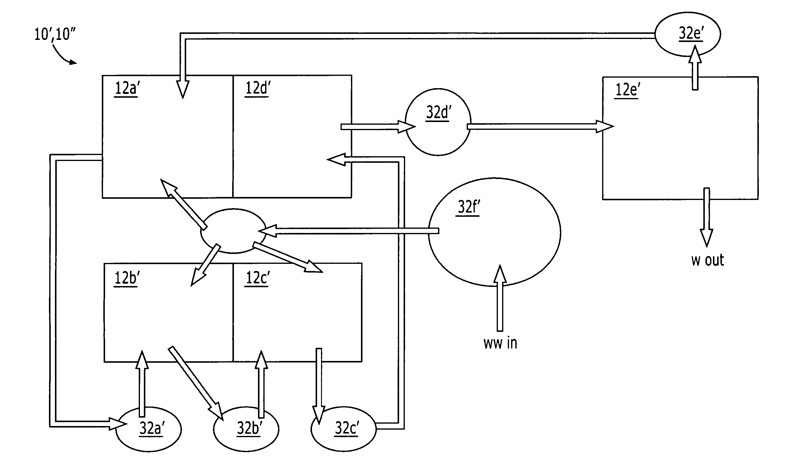
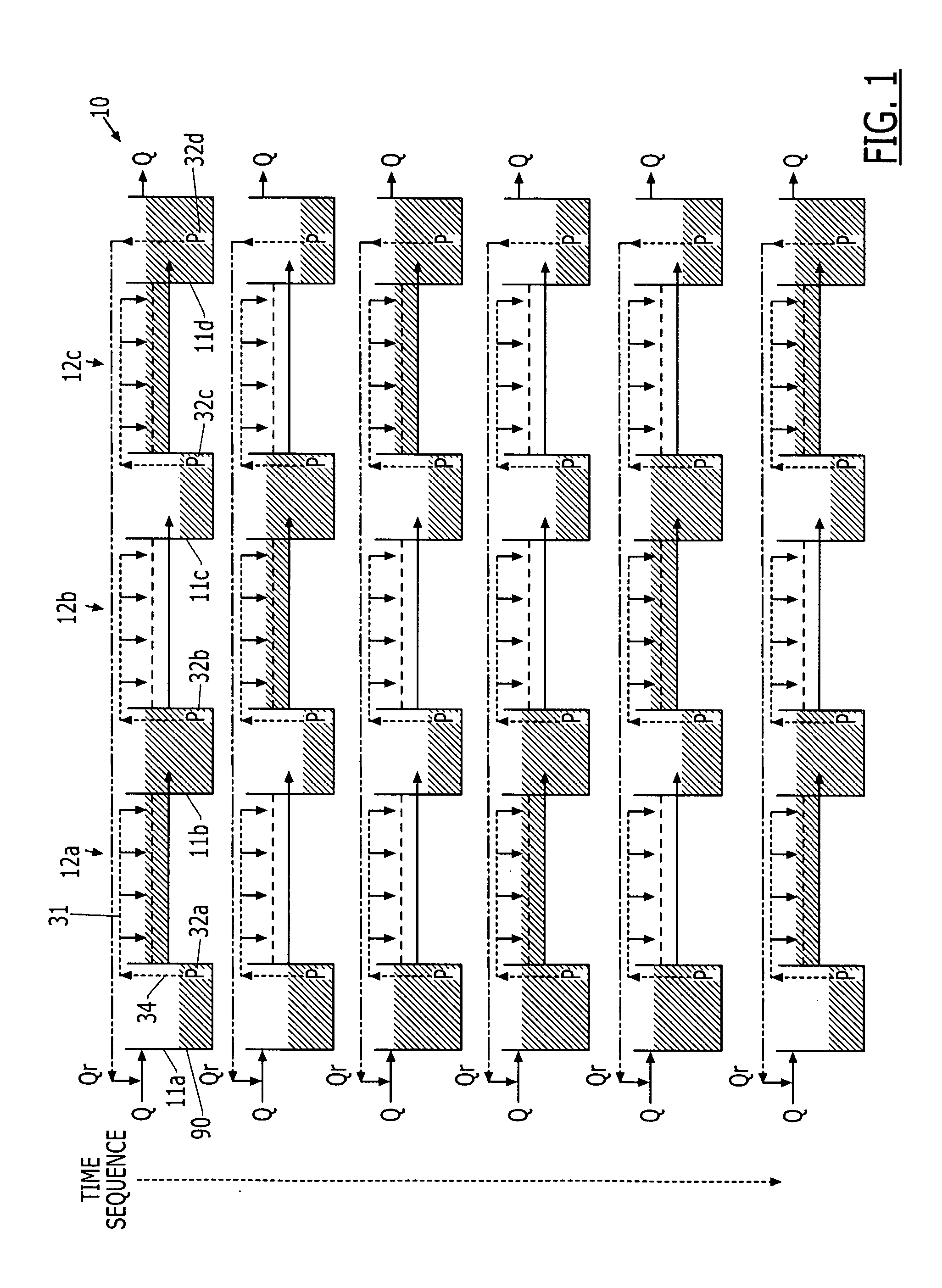
[0047] The integrated TVFM treatment system 10 in a particular embodiment comprises an alternating series of lagoons 11 and VF marsh cells 12, for example, marsh cells 12a-12c and lagoons 11a-11d, alternating as shown in FIG. 1. Q represents forward flow; Qr, recycle flow. The overflow piping between marsh cells 12a-12c and lagoons 11a-11d is not depicted. The dashed horizontal line in the marsh cells 12a-12c represents the media / plant root surface. The overall hydraulic regime in the system 10 involves fill and drain cycles where wastewater is alternately pumped and flows between cells 12 and lagoons 11. The tidal vertical flux of water in and out of the marsh cells 12a-12c is designed to cycle over a predetermined period of, for example, at least once per day.

[0048] Means for transporting water between the lagoons 11a-11c and marsh cells ...


PUM

PropertyMeasurementUnit
concentrationsaaaaaaaaaa
concentrationaaaaaaaaaa
diameteraaaaaaaaaa

Abstract

A wastewater treatment system includes a tidal, sequential vertical flow marsh cell system having at least three marsh cells in serial forward fluid communication. Incoming wastewater to be treated is channeled to at least the first and a second marsh cell, and a portion of water exiting a final marsh cell, to the first marsh cell surface. Each marsh cell is alternately flooded and drained for enhancing aeration of incoming water and marsh cell contents, which include media and plant roots having biofilms growing thereon, the biofilms including a population of nitrifying and denitrifying bacteria, for achieving substantially simultaneous nitrification and denitrification of the wastewater.

Description

CROSS-REFERENCE TO RELATED APPLICATIONS [0001] This application is a continuation of application Ser. No. 10 / 463,199, filed Jun. 17, 2003, which itself is a continuation-in-part of application Ser. No. 10 / 377,287, filed Feb. 28, 2002, which claims priority to Provisional Application 60 / 389,398, filed Jun. 17, 2002. The disclosures of these applications are incorporated by reference hereinto.BACKGROUND OF THE INVENTION [0002] 1. Field of the Invention [0003] The present invention relates generally to wastewater treatment systems and methods, and, more particularly, to such systems and methods using bioremediation techniques. [0004] 2. Related Art [0005] Engineered wetlands for wastewater treatment are known to have three basic hydraulic configurations: surface flow (SF), subsurface horizontal flow (SSHF), and vertical flow (VF), the first two believed the most common, and are known to have significant design shortcomings. Even though an early wastewater treatment wetland design utili...

Claims


Application Information

Patent Timeline
Patent Type & Authority Applications(United States)
IPC IPC(8): C02F3/32
CPCC02F3/302Y10S210/903C02F3/327Y02W10/10
Inventor AUSTIN, DAVID C.LOHAN, ERIC
Owner IASIS USA LC
Why Eureka
Try Eureka