Pressure exchange ejector
a technology of pressure exchange ejector and ejector chamber, which is applied in the direction of machines/engines, mechanical equipment, light and heating apparatus, etc., can solve the problems of low efficiency, high cost, and the need for high-precision products for equivalent turbo-machinery, so as to reduce the mechanical complexity of prior art pressure-exchange ejectors and achieve high efficiency. , the effect of reducing the mechanical complexity of prior art pressure-exchange ejector
- Summary
- Abstract
- Description
- Claims
- Application Information
AI Technical Summary
Benefits of technology
Problems solved by technology
Method used
Image
Examples
second embodiment
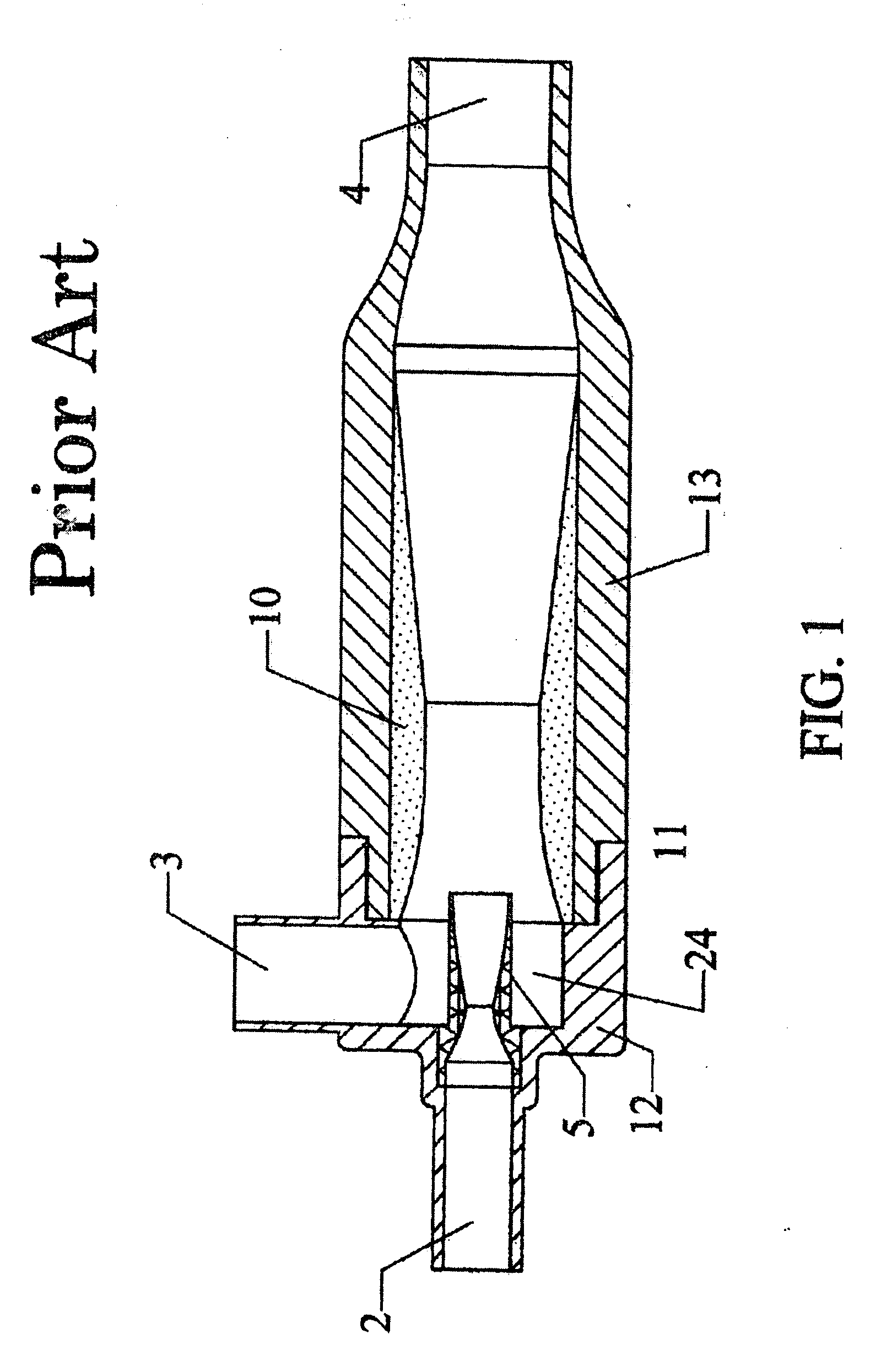
[0045] In the invention, the pressure exchange ejector is designed for the transport of subsonic fluids, particularly liquids. Referring to FIG. 3, in such an application, the best mode would require that the nozzle 5 be converging, and the secondary fluid inlet plenum 24 would most likely be coaxial with the nozzle 5. The configuration of the fore-body 6 and the rotor vanes 18 would be similar, however, it is anticipated that the transitions from the fore-body 6 to the ramp-shaped vanes 18, and the transition from the vanes to the centerbody 14 would be gradual rather than abrupt, consistent with standard subsonic design. The shroud 10, would have a similar shape as with the supersonic case, and the shroud 10 diameter being sufficient to allow the secondary fluid to pass and enter the interstices between the primary fluid pseudo-blades. As with the supersonic case, the vane-angles should be designed to produce the “free-spinning” rotational speed. However, due to the slower subsoni...
third embodiment
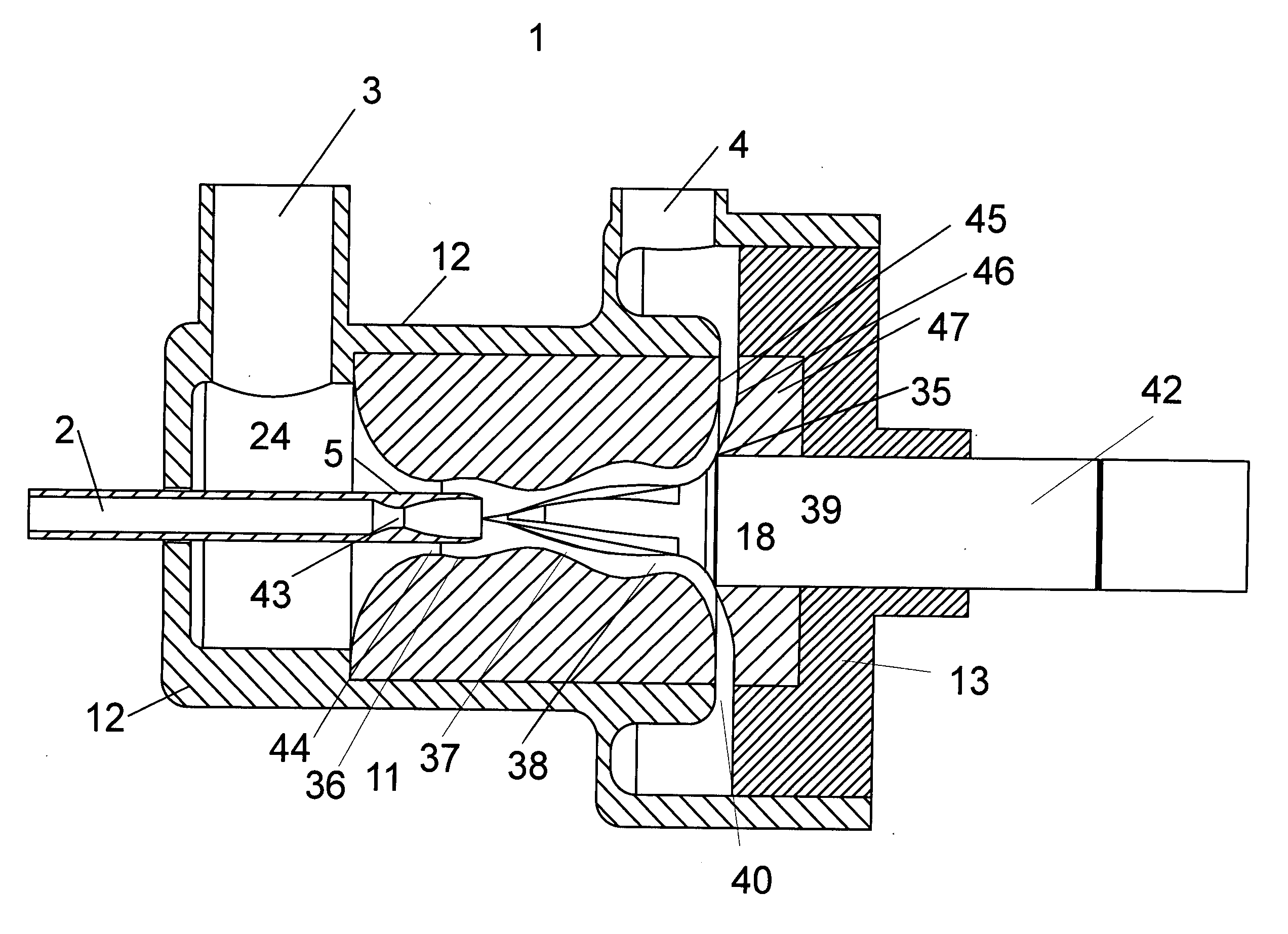
[0047] A third preferred embodiment is shown in FIGS. 14-21. In FIG. 17 is shown a pressure exchange ejector having a housing 1 comprising and upstream portion 12 and a downstream portion 13. Said upstream portion of housing 12 fixedly supports inlet conduit 2 which is shown integral with primary fluid nozzle 5. A compressible primary fluid is introduced through inlet conduit 2 and passes through supersonic primary nozzle 5. Said upstream portion of said housing 12 also includes a secondary fluid inlet conduit 3 and an outlet conduit 4 for the mixed fluid. The mass flow rate of nozzle 5 is determined by the cross-sectional area of the first throat 43 and the properties and thermodynamic conditions of the primary fluid. If the working fluid were to be air at a total temperature of 300° K., the nozzle 5 shown in FIG. 17 would result in an exit fluid Mach number of 3.0 if the primary total pressure exceeded the critical value to produce choked flow at the throat of the nozzle. Clearly ...
first embodiment
[0048] A rotor 7, configured to rotate about its central axis, is placed with said axis of rotation coaxial with the central axis of said supersonic primary nozzle 5 immediately downstream of a conical forebody 6, the apex of which is approximately situated at the exit plane of said primary nozzle 5. The rotor 7 is pivotally mounted on the shaft of a spindle 42. Said spindle 42 is rigidly supported and sealed by said downstream portion of housing 13. Said spindle 42 may be motorized, but in the preferred embodiment, the rotor is self-driven aerodynamically so that said spindle only contains radial and thrust bearings and a pivotal output shaft (not shown.) In the preferred embodiment, these bearings should be as frictionless as possible. Gas bearings or compliant foil bearings are considered preferable to more conventional bearings. The half-angle of the conical forebody 6 shown in this embodiment is 10°. The rotor 7 of this embodiment is shown in detail in FIGS. 14, 15, and 16. In ...
PUM
 Abstract
Description
Claims
Application Information
 - R&D
- Intellectual Property
- Life Sciences
- Materials
- Tech Scout
- Unparalleled Data Quality
- Higher Quality Content
- 60% Fewer Hallucinations
Browse by: Latest US Patents, China's latest patents, Technical Efficacy Thesaurus, Application Domain, Technology Topic, Popular Technical Reports.
© 2025 PatSnap. All rights reserved.Legal|Privacy policy|Modern Slavery Act Transparency Statement|Sitemap|About US| Contact US: help@patsnap.com


