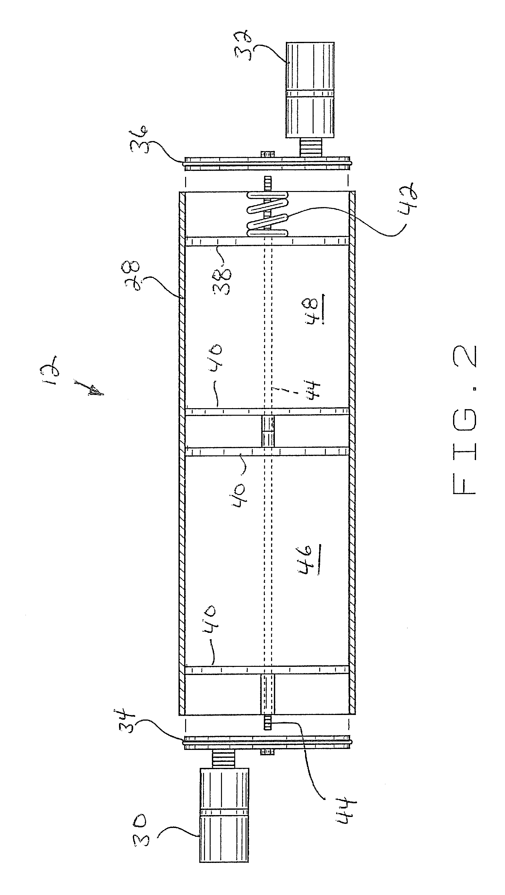
[0010] The present filter / absorption member is used to both dry the
nitrogen as it is being supplied from the
nitrogen source and to filter and purify the nitrogen prior to entry into a particular tire. This is accomplished through the use of two
molecular sieve beds associated with the filter / absorption member. As the nitrogen enters the filter / absorption member, it is first introduced into a Z3-06
molecular sieve bed which acts as a
drying agent for pulling and absorbing any
moisture associated with the nitrogen as it is passed through this portion of the filter / absorption member. Any moisture associated with the nitrogen will be selectively absorbed into the Z3-06 material and the remaining nitrogen is then passed into a carbon
molecular sieve bed for final preparation before entry into the present valving mechanism. As the nitrogen enters the carbon molecular
sieve bed, the carbon material purifies the remaining nitrogen and absorbs all other gases or other contaminants associated with the nitrogen leaving dry and purified nitrogen available for use during the purging / filling operation as will be hereinafter further explained. Although various types of filter / absorption systems can be used in association with the present apparatus, use of a two-stage filter / absorption member which both dries and purifies the nitrogen before introduction into a racing tire greatly improves the consistency and purity of the nitrogen being used in each application.
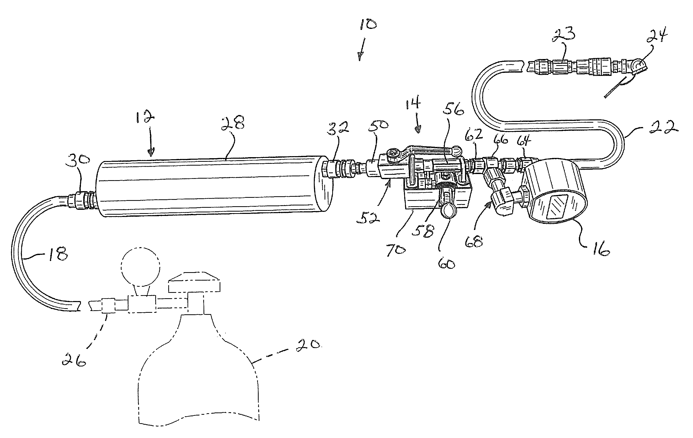
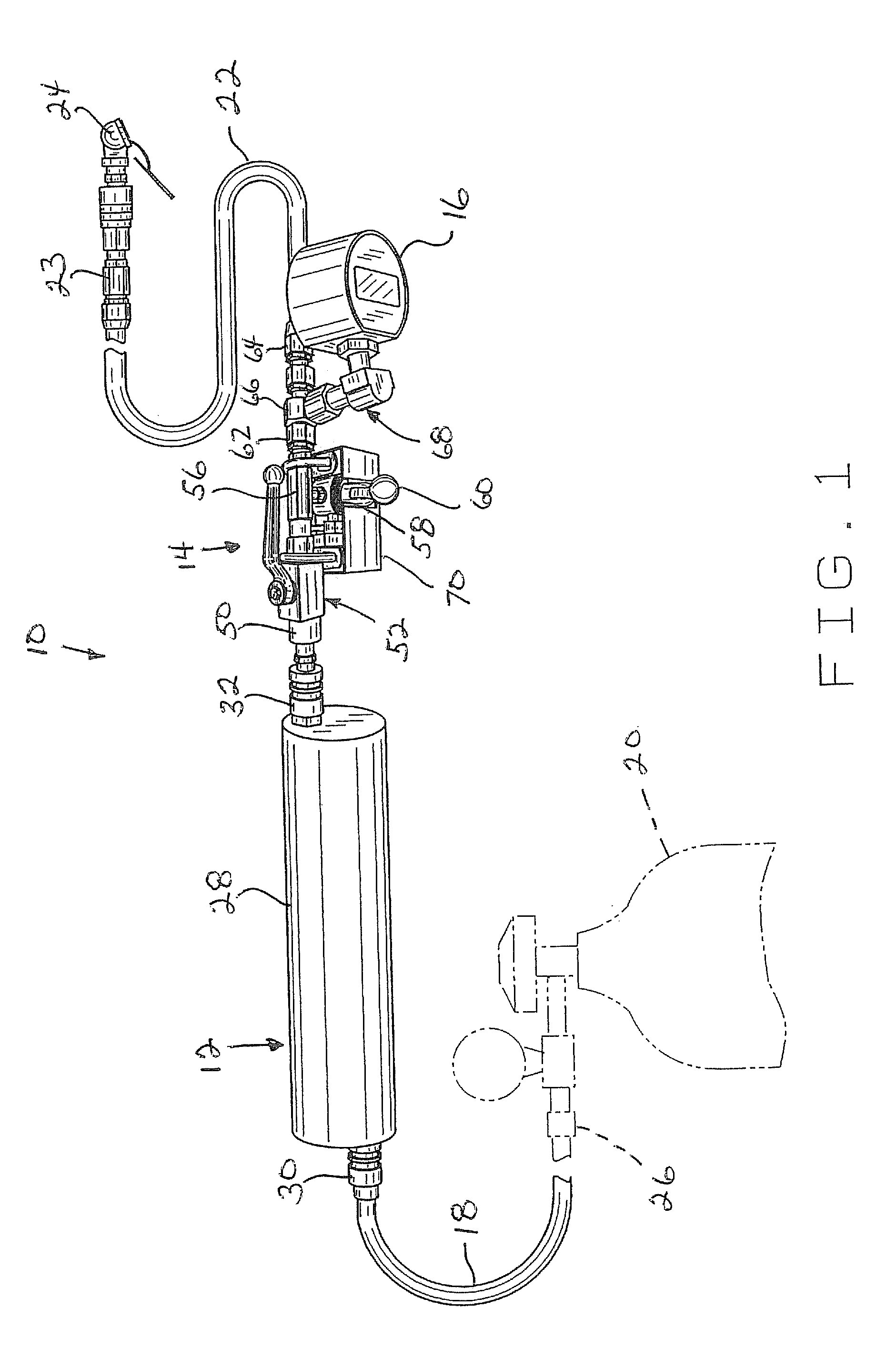
[0012] With the on / off valve in its “on” position, dried and purified nitrogen will continue to flow through a pneumatic
vacuum pump enroute to the tire to be filled. A two-way diverter valve is associated with the
vacuum pump and includes a selectively positionable two position switch. When the diverter valve is in a first position, the vacuum pump remains in its off position and nitrogen is allowed to flow through the vacuum pump and through appropriate hoses and connections to the tire to be filled. When in its second position, the two-way diverter valve allows the vacuum pump to draw a vacuum on the tire to be filled so as to purge the tire of air and other contaminants. An exhaust port is associated with the diverter valve or the vacuum pump for allowing air and other contaminants drawn from the tire to be easily purged and exhausted from the present mechanism.
[0013] Because the two-way diverter valve is easily operated by a user through the use of an easily manipulated two position switch, both purging and filling a particular tire with nitrogen can be easily and quickly accomplished without repeatedly removing the
valve stem associated with the tire to be filled during successive evacuation and fill operations. For example, once a tire has been bled of all pressurized air and the
valve stem has been replaced, the present apparatus is attached to the valve portion of the tire and the tire can be further purged of
atmospheric air and other contaminants by moving the on / off valve to the “on” position and by moving the two-way diverter valve to the “vacuum” or “purge” position. Once the tire has been initially purged and evacuated of
atmospheric air and other contaminants, the tire can now be easily filled with nitrogen by simply moving the two-way diverter valve to its “fill” position. Once the tire has been filled with nitrogen, to a predetermined pressure, the two-way diverter valve can again be immediately positioned to its “vacuum” or “purge” position whereby nitrogen and any other gases or contaminants contained within the tire will again be purged from the tire and exhausted through the exhaust port associated with the diverter valve. The tire can be at least partially evacuated of nitrogen and any other gases or contaminants contained therein and can then immediately be refilled by simply repositioning the diverter valve to the “fill” position. As a result, successive intervening purging and filling of the same tire can be accomplished in a matter of seconds or minutes without removing the valve stem associated with the respective tire.
[0014] In another aspect of the present invention, there is disclosed a tire purge / fill apparatus which includes a filter / absorption member, a pressure
relief valve positioned between the supply of
nitrogen gas and the filter member for monitoring and controlling the pressure of the gas being supplied to the remainder of the
system, a
pressure regulator positioned between the pressure
relief valve and the filter member for controlling the pressure of the
nitrogen gas being introduced into the filter member, a valve mechanism which includes a single user selectable joy stick
handle member for controlling both the purging and filling operation, a pressure gauge for monitoring the tire pressure during a filling operation, and appropriate hoses and
coupling devices for operatively connecting the present apparatus to the
nitrogen source and to a respective tire or tires to be filled. In this particular embodiment, the valve mechanism includes a three position joy stick
handle member which is moveable to a first position wherein the valve mechanism is closed and no purging or filling of a respective tire can occur, to a second position wherein a filling operation can occur, and to a third position wherein the vacuum pump is activated and a purging operation can occur. Use of a single three position joy stick type
handle member or other user selectable member replaces the on / off valve and the two-way diverter valve associated with the first valve mechanism embodiment and greatly simplifies the purging and filling operations. This embodiment likewise includes a convenient carrying
assembly for transporting the present apparatus from one location to another including a removable cover member for accessing operation of the valve mechanism.
[0016] Use of the present tire purge / fill apparatus allows an operator to quickly change from a purging operation to a filling operation without manually removing the valve stem from each respective tire to be filled between each intervening purging / refilling operation. Also, because of the two-stage filter / absorption member associated with the present apparatus,
drying and purifying the nitrogen before entry into a particular tire is more effectively accomplished thereby improving and increasing the consistency and purity of the nitrogen being provided to each respective tire. The present invention also teaches a method for inflating racing tires which substantially reduces the overall time in effectively filling such tires to a predetermined pre-race tire pressure.

