Isothermal reciprocating machines

a reciprocating machine and reciprocating technology, applied in the field of reciprocating machines, can solve the problems of energy cost of gas compression, and achieve the effects of relaying heat, high heat capacity material, and large surface area

Inactive Publication Date: 2006-11-09
MA THOMAS TSOI HEI
View PDF10 Cites 135 Cited by
  • Summary
  • Abstract
  • Description
  • Claims
  • Application Information

AI Technical Summary

Benefits of technology

[0020] An open matrix heat regenerator constructed in fine mesh or thin wall cell structure of high heat capacity material is additionally provided occupying the clearance space in the cylinder and in intimate thermal contact with the gas inside the cylinder. The heat regenerator serves efficiently to absorb and store heat from the filled gas (heat transfer fluid) during the extra filling and emptying strokes of the extended cycle, and to release the stored heat to the expanding gas (working fluid) during the next expansion stroke.
[0021] In the invention, by using warm air or warmed expelled working fluid as heat transfer fluid to transfer external heat to the cylinder, piston and heat regenerator and raise the temperature of the cylinder and heat regenerator close to the temperature of the warm air during the extra filling and emptying strokes, the admitted working fluid of high pressure gas expanding (and potentially cooling) during the next expansion stroke will be warmed progressively by the heat regenerator and stay at substantially the same temperature as the heat regenerator, thus enab

Problems solved by technology

In many cases, the energy cost of gas compression is a major

Method used


Image

  • Isothermal reciprocating machines
  • Isothermal reciprocating machines
  • Isothermal reciprocating machines

Examples


Embodiment Construction

[0052] In the description, numeric annotations are specific for each Figure and not carried over to other Figures.

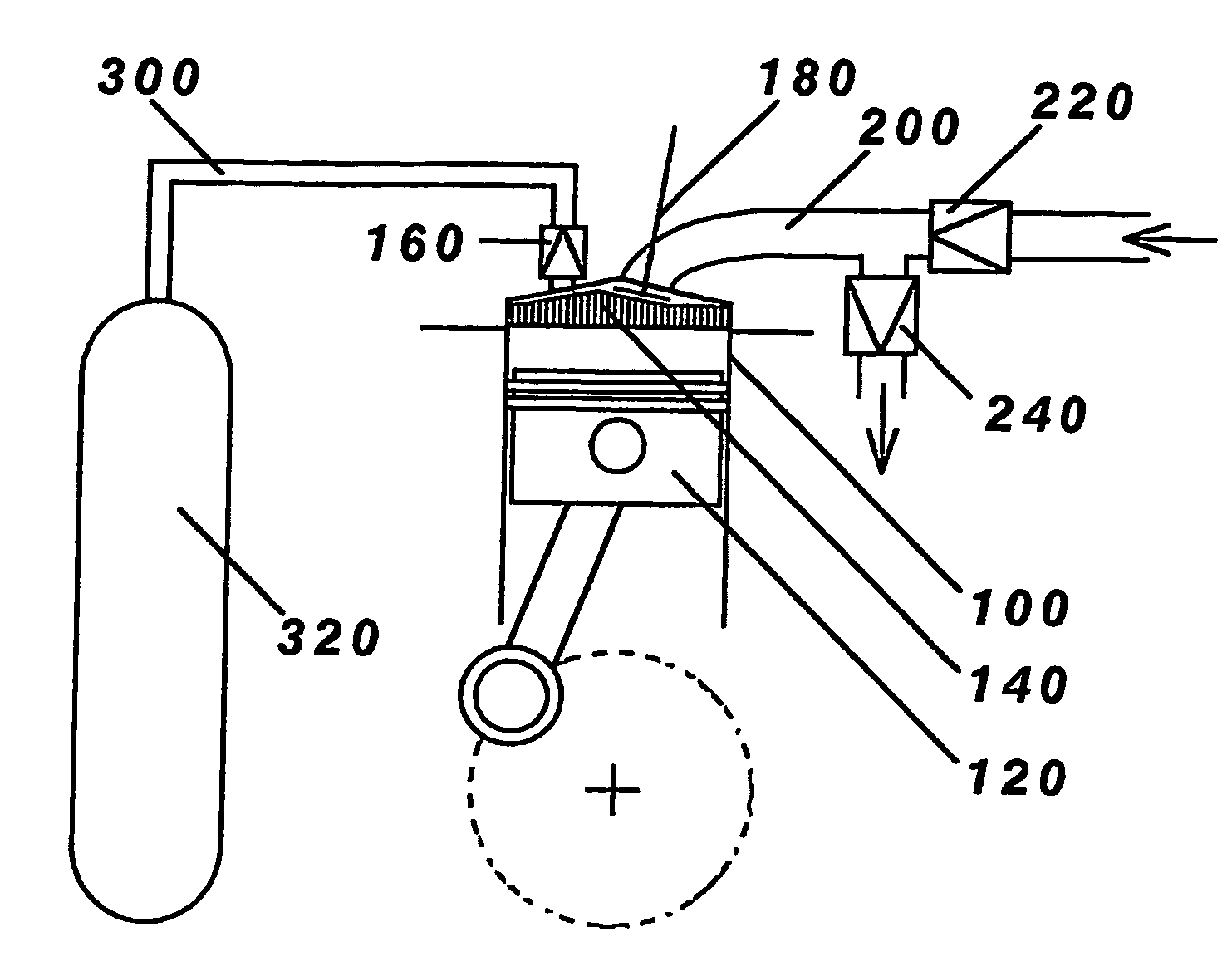
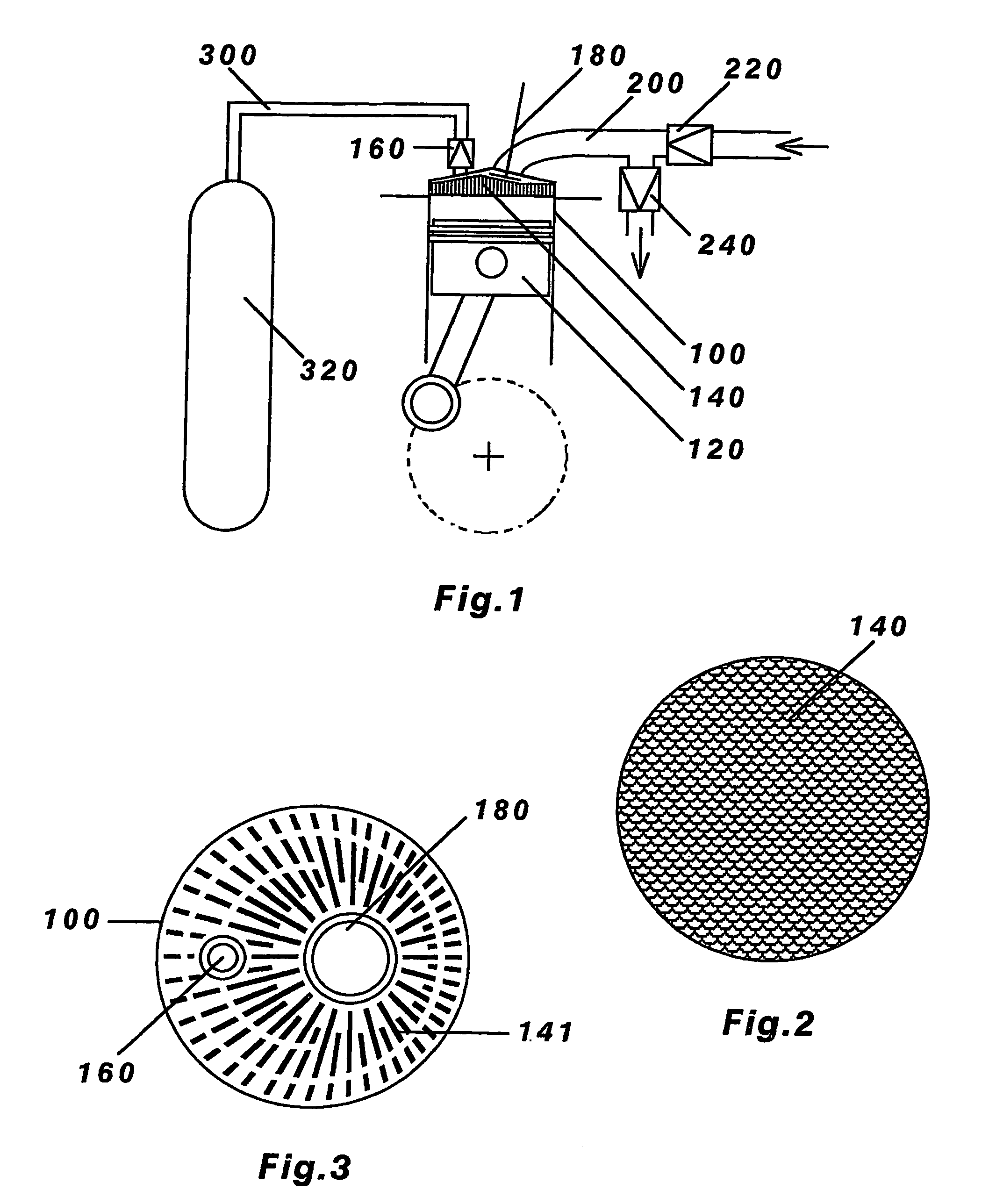
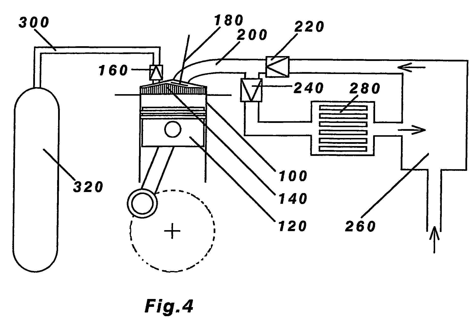
[0053]FIG. 1 shows a reciprocating air compressor comprising at least one cylinder 100 having a variable volume defined by a reciprocating piston 120 which draws ambient air (working fluid) into the cylinder 100 during the induction stroke and compresses the air to a high pressure before the air is released through a non-return valve 160 to a high pressure air reservoir 320 during the compression stroke. The reciprocating air compressor is further equipped to operate according to an extended cycle comprising after the said induction and compression strokes, at least one pair of extra strokes each pair consisting of a filling stroke in which more ambient air (heat transfer fluid) is drawn by the piston 120 (as shown by the ingoing arrow) into the cylinder 100 to fill the cylinder 100 followed immediately by an emptying stroke in which the filled air is expelled by the pi...


PUM


Abstract

A reciprocating gas compressor is described operating according to an extended cycle of 4,6 or more strokes, wherein the first two strokes are sequential induction and compression strokes using a low pressure gas as working fluid and compressing it to a high pressure gas, and the remaining strokes are pairs of sequential filling and emptying strokes using more of the low pressure gas as heat transfer fluid for transferring heat from inside the gas compressor to outside the gas compressor. The gas compressor also contains an in-cylinder heat regenerator for absorbing heat from the compressed gas and releasing heat to the heat transfer fluid thus achieving near-isothermal compression. Using parallel principles, a reciprocating gas expander is also described for achieving near-isothermal expansion. Also described are reciprocating machines using the near-isothermal gas compressor and near-isothermal gas expander in combination according to the Ericsson heat engine cycle, the Stirling heat engine cycle and the Stirling refrigeration cycle.

Description

FIELD OF THE INVENTION [0001] The present invention relates to reciprocating machines capable of near-isothermal compression and expansion. BACKGROUND OF THE INVENTION [0002] The reciprocating gas compressor has been used extensively throughout industry for compressing gases to high pressure. Applications include a wide spectrum from heavy duty units in gas and oil fields, power generation plants, gas separation plants, chemical processing plants, refrigeration and gas liquefaction plants, manufacturing and production plants, construction industry etc, to light duty units for automotive, laboratory and domestic uses. In many cases, the energy cost of gas compression is a major factor determining the economics of the process or the plant. This in turn depends on the efficiency of the compressor. [0003] The efficiency of the compressor typically lies between a lower limit where the compression process is adiabatic and an upper limit where the compression process is isothermal, the lat...

Claims


Application Information

Patent Timeline
IPC IPC(8): F02G1/04
CPCF04B25/00F25B2309/1401F04B39/06
Inventor MA, THOMAS TSOI HEI
Owner MA THOMAS TSOI HEI
Why Eureka
Try Eureka