Use of an osmotic pump to create a flowing reference junction for ionic-activity sensors

a reference junction and ionic-activity sensor technology, applied in the field of ionic-activity sensors, can solve the problems of compromising the liquid junction and the half-cell potential, poor results obtained from ion-selective electrode measurements, etc., and achieves the effect of increasing the volume of osmotic-agent solution, relatively small and long-lasting, and initial ra

Inactive Publication Date: 2006-11-09
INVENSYS SYST INC
View PDF35 Cites 9 Cited by
  • Summary
  • Abstract
  • Description
  • Claims
  • Application Information

AI Technical Summary

Benefits of technology

[0008] In a typical embodiment, the osmotic pump will include a solvent reservoir containing a solvent, an osmotic-agent reservoir that contains an osmotic agent and is disposed in fluid communication with the solvent reservoir through a diffusion path, a semi-permeable osmotic membrane interposed in the diffusion path, and an actuator so operatively coupled to the osmotic-agent reservoir and the flowing electrolyte as to be urged by expansion of the osmotic-agent reservoir to drive the reference-cell electrolyte through the reference half cell's external junction. The semi-permeable osmotic membrane is more permeable to diffusion of the solvent than to the osmotic agent, so flow from the solvent side to the osmotic-agent side tends to predominate, thereby increasing the volume of osmotic-agent solution and resulting in the actuator's driving the electrolyte.
[0009] It turns out that an osmotic pump is particularly advantageous in this context, because it lends itself naturally to being implemented in embodiments whose flow-rate change throughout the sensor's lifetime is, for a given temperature, minimal. Specifically, the osmotic-agent reservoirs is a typical embodiment of this type will include a

Problems solved by technology

However, in this configuration both the liquid junction and the half-cell potential may be compromised during ingress of the process solution into the internal salt-bridge an

Method used


Image

  • Use of an osmotic pump to create a flowing reference junction for ionic-activity sensors
  • Use of an osmotic pump to create a flowing reference junction for ionic-activity sensors
  • Use of an osmotic pump to create a flowing reference junction for ionic-activity sensors

Examples


Embodiment Construction

[0020] The invention is applicable to devices that include a reference electrode for use with electrochemical ion measuring electrodes, for example, pH electrodes, and employ a flowing reference-cell electrolyte.

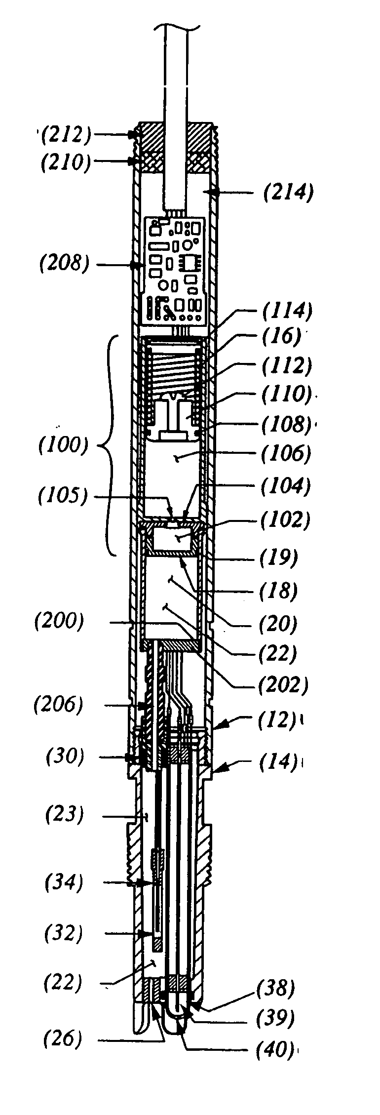
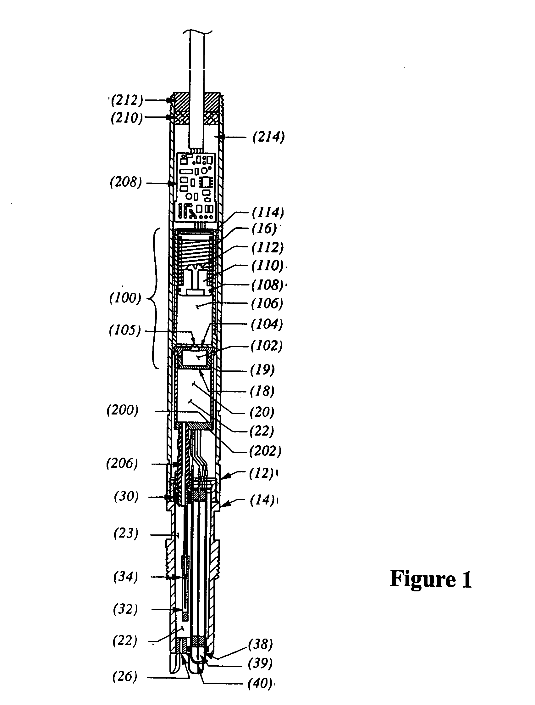
[0021]FIG. 1 depicts one such device. The FIG. 1 device, which is a pH sensor, includes an upper housing 12 and a lower housing 14. Located in the upper housing 12 is a delivery-fluid reservoir 20 for an electrolyte 22. As will be explained in due course, this electrolyte flows past a reference half cell 34. In the illustrated embodiment, the reference half cell 34's electrode is encased by an internal junction 32, which may be a cation-exchange membrane. The cation-exchange membrane may be a sulphonated polytetrafluoroethylene membrane, for example, commercially available membrane from DuPont under the trade name NAFION®. A glass membrane 40 surrounds the sensor's measuring electrode 39. A pre-amplifier board 208 receives the reference and measuring electrodes' outputs and...


PUM


Abstract

In an ionic-activity sensor, an osmotic pump drives a reference-cell electrolyte to flow through an interface with the solution to be measured. This minimizes contamination of the reference cell by that solution. The driving force results from expansion of an electrolytic-agent reservoir into which solvent from a solvent reservoir diffuses through a semi-permeable membrane. The electrolytic-agent reservoir contains an electrolytic-agent solution in which a quantity of undissolved is disposed to keep the electrolytic-agent solution saturated as solvent diffuses into it.

Description

BACKGROUND OF THE INVENTION [0001] 1. Field of the Invention [0002] The present invention concerns ionic-activity sensors, particularly of the flowing-electrolyte type. [0003] 2. Background Information [0004] A basis of ionic-activity (electrochemical) measurements, including, for example, measurements of oxidation-reduction potential and of ionic-concentration such as pH, is the development of a potential difference across a membrane of a specific composition interposed between different solutions. In the case of pH measurements, for example, one measures the development of a potential gradient across a membrane when the sensor is interposed between solutions having different hydrogen-ion activities. In this example, the potential developed across the membrane is quantitatively related to the activity gradient of hydrogen ion and can be applied to a known measuring circuit to measure the pH of the sample. Because the potential developed across the glass is measured, electrolytic co...

Claims


Application Information

Patent Timeline
IPC IPC(8): G01N27/26
CPCG01N27/4035
Inventor BOWER, MICHAEL M.CATALANO, LAUREN M.CONNELLY, JOHN P.TALUTIS, STEPHEN B.TOWER, DANIEL G.BISCHOFF, BRIAN J.
Owner INVENSYS SYST INC
Why Eureka
Try Eureka