Bandstop filter

a filter and bandstop technology, applied in the field of high-frequency filters, can solve the problems of imposing a limit on the stop bandwidth, unable to guarantee that the size of the gap necessarily becomes the desired size, and it is more difficult to obtain a large joint, so as to achieve the effect of improving production yield and variability in characteristics

Inactive Publication Date: 2006-11-09
MITSUBISHI ELECTRIC CORP
View PDF1 Cites 15 Cited by
  • Summary
  • Abstract
  • Description
  • Claims
  • Application Information

AI Technical Summary

Benefits of technology

[0010] The present invention has been made to solve the above problems, and has an object to provide a bandstop filter with which variation in characteristics is suppressed to minimum and a production yield is improved.

Problems solved by technology

However, the conventional technique has the following problems.
In addition, because of the producable minimum size, production errors, and the like, it is not guaranteed that the size of the gap necessarily becomes a desired size.
This imposes a limitation on the stop bandwidth that is realizable with a produced filter.
In particular, when the conventional bandstop filter is constructed using a planar circuit such as a microstrip line or a strip line, there arise the following problems.
That is, a strip conductor corresponding to the inner conductor described above has an extremely thin thickness, which makes it more difficult to obtain a large joint.
When a gap for realizing a desired stop bandwidth is reduced and approaches a limitation in terms of production, a problem of variation in gap due to a production error or variation in width due to a production error of two strip conductors becomes more prominent.
However, it is difficult to adjust the distance between the strip conductors after formation because they are formed through etching or the like.
Therefore, the variation in characteristics due to the production error directly leads to a filter yield reduction.
In addition, the conventional bandstop filter has a problem in that a production error in short-circuiting means of the resonator directly leads to variation in filter characteristics.
In such a case, there is a problem in that when the positional relation between the strip conductor and the through hole (via hole) changes due to a problem in terms of production, a resonance frequency is shifted and there occurs characteristic deterioration such as variation in stop band.

Method used


Image

  • Bandstop filter
  • Bandstop filter
  • Bandstop filter

Examples


first embodiment

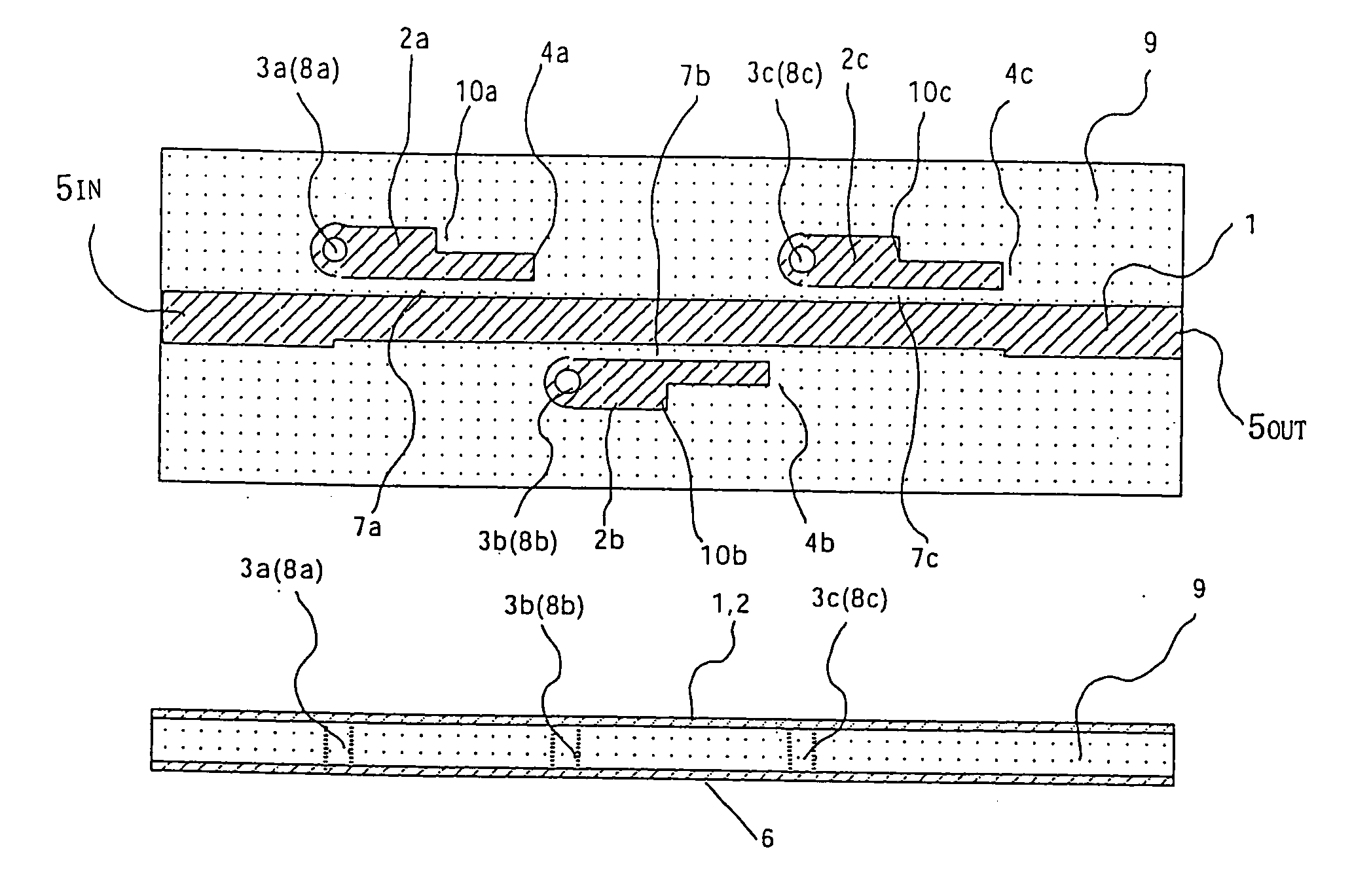
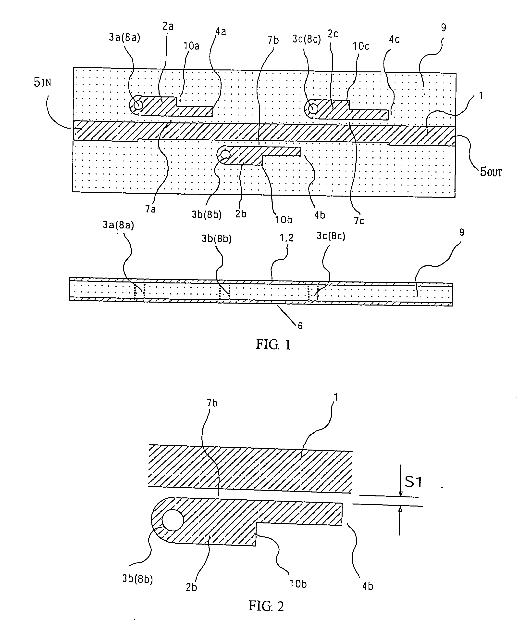
[0026]FIG. 1 is an internal construction diagram of a bandstop filter according to the first embodiment of the present invention, with a view from above and a cross-sectional view being illustrated. In FIG. 1, a bandstop filter including three resonators is illustrated. Each construction element of the first resonator is given a reference numeral with a suffix “a” and suffixes “b” and “c” are used for the second and third resonators in a like manner. Note that in the following description, when an explanation that is common to the three resonators is made, only reference numerals, from which the suffixes are removed, are used.

[0027] The bandstop filter of the first embodiment is a three-stage filter having a microstrip line structure constructed using one dielectric substrate 9. An input signal to be bandstopped is taken into the bandstop filter from an input terminal 5IN, passes through a strip conductor 1 of a main line, and is finally outputted as a bandstopped signal from an ou...

second embodiment

[0042]FIG. 6 is an internal construction diagram of a bandstop filter according to a second embodiment of the present invention, with a view from above and a cross-sectional view being illustrated. Also, FIG. 7 is an equivalent circuit diagram of the bandstop filter according to the second embodiment of the present invention. The fundamental structure is the same as that of the bandstop filter in the first embodiment. The second embodiment differs from the bandstop filter in the first embodiment in the following two points. That is, the number of stages of the filter is reduced to one and a tip-end open transmission line 11 having an approximately ¼ wavelength is used in place of the short-circuiting means.

[0043] The bandstop filter of the second embodiment performs fundamentally the same operation as in the first embodiment. The tip-end open transmission line 11 having the approximately ¼ wavelength is used in place of the short-circuiting means and is placed under an open state b...

third embodiment

[0046]FIG. 8 is an internal construction diagram of a bandstop filter according to a third embodiment of the present invention, with a view from above and a cross-sectional view being illustrated. Also, FIG. 9 is an equivalent circuit diagram of the bandstop filter according to the third embodiment of the present invention. The fundamental structure is the same as that of the bandstop filter in the second embodiment. The third embodiment differs from the bandstop filter in the second embodiment in that an impedance non-continuous structure portion 13 is provided for the tip-end open transmission line 11 in the second embodiment.

[0047] The bandstop filter of the third embodiment performs fundamentally the same operation as in the second embodiment and provides fundamentally the same effect as in the second embodiment. In the bandstop filter of the third embodiment, the second impedance non-continuous structure portion 13 is provided for the tip-end open transmission line 11 that is ...


PUM


Abstract

A bandstop filter where variation in characteristics is suppressed to minimum and which realizes an increased production yield. The physical length of a line joint portion between a main line and an oscillator can be enlarged by providing an impedance non-continuous structure portion in a strip conductor of the oscillator. In comparison to the case where the impedance non-continuous structure portion is not provided, the width of a joint slit required to obtain an equal joint amount can be enlarged. When the joint slit width is enlarged, variation in filter characteristics caused by pattern accuracy can be reduced because of the enlarged joint slip width, thus improving a filter yield. This means that pattern accuracy requirement for production is loosened. Freedom in selecting a dielectric substrate is increased, which also provides an advantage that a filter can be produced using a less expensive dielectric substrate with not very high pattern accuracy.

Description

BACKGROUND OF THE INVENTION [0001] 1. Field of the Invention [0002] The present invention relates to a high-frequency filter used in a microwave band and a millimeter-wave band. [0003] 2. Description of the Related Art [0004] With a bandstop filter described in a document entitled “Exact Design of Band-stop Microwave Filters” (written by B. M. Schiffman and G L. Matthaei in IEEE Trans. on MTT, vol. MTT-12, pp 6-15 (1964)), for instance, by reflecting a signal in a frequency band in which the electrical length of an inner conductor of a resonator becomes approximately 90 degrees, passage of the signal in the frequency band is inhibited. [0005] In the case of this bandstop filter, a frequency, at which the resonator resonates, becomes the center frequency of a stop band. Also, a gap of a portion, in which the inner conductor of the resonator and an inner conductor of a main line are arranged parallel to each other and constitute a line joint, corresponds to the stop bandwidth of the f...

Claims


Application Information

Patent Timeline
Patent Type & Authority Applications(United States)
IPC IPC(8): H01P1/203
CPCH01P1/2039
Inventor OHWADA, TETSUOSAKADA, HIROSHIOH-HASHI, HIDEYUKI
Owner MITSUBISHI ELECTRIC CORP
Why Eureka
Try Eureka