

Optical recording/reproducing method and optical recording medium
- Summary
- Abstract
- Description
- Claims
- Application Information
AI Technical Summary
Benefits of technology
Problems solved by technology
Method used
Image

Examples
working examples
[0114] In Working Examples described below, optical recording disc samples were evaluated using an optical recording disc evaluating apparatus “DDU1000” manufactured by Pulstec Industrial Co., Ltd. in which a low resolution pick up (the resolution limit pitch was 530 nm and the resolution limit length was 265 nm) constituted so that a laser beam having a wavelength λ of 635 nm was emitted from an optical system having a numerical aperture of 0.60 and a high low resolution pick up (the resolution limit pitch was 312 nm and the resolution limit length was 166 nm) constituted so that a laser beam having a wavelength λ of 405 nm was emitted from an optical system having a numerical aperture of 0.65 were provided so as to face each other. A linear recording velocity used when data were to be recorded or data were to be reproduced was 6 m / sec.
[0115] In this optical recording disc evaluating apparatus, a laser beam emitted from the low resolution pick up enters the noble metal oxide layer...
working example 1-1
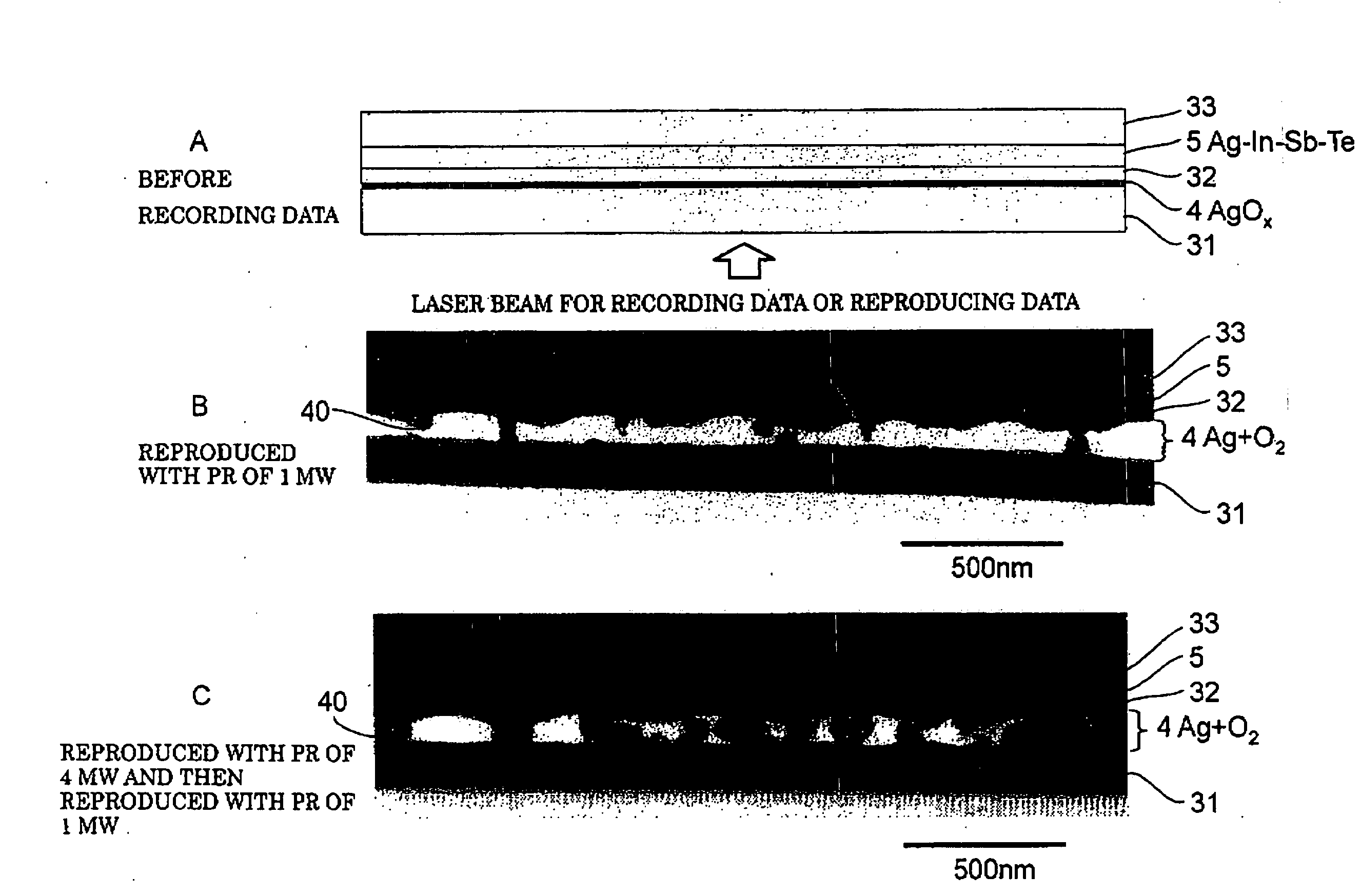
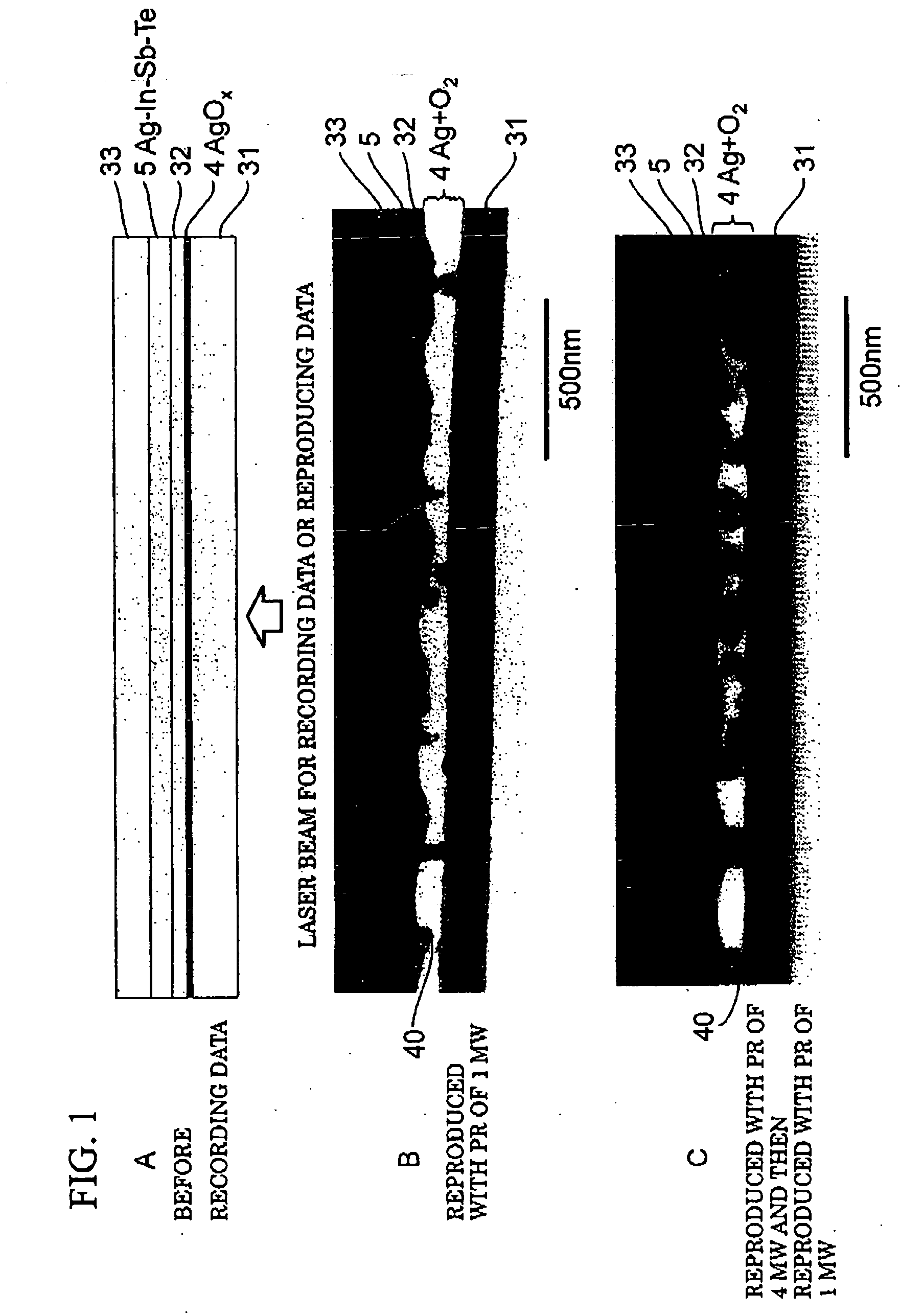
The Optical Recording Medium Having the Structure Shown in FIG. 2 and the Noble Metal Oxide Layer Containing AgOx
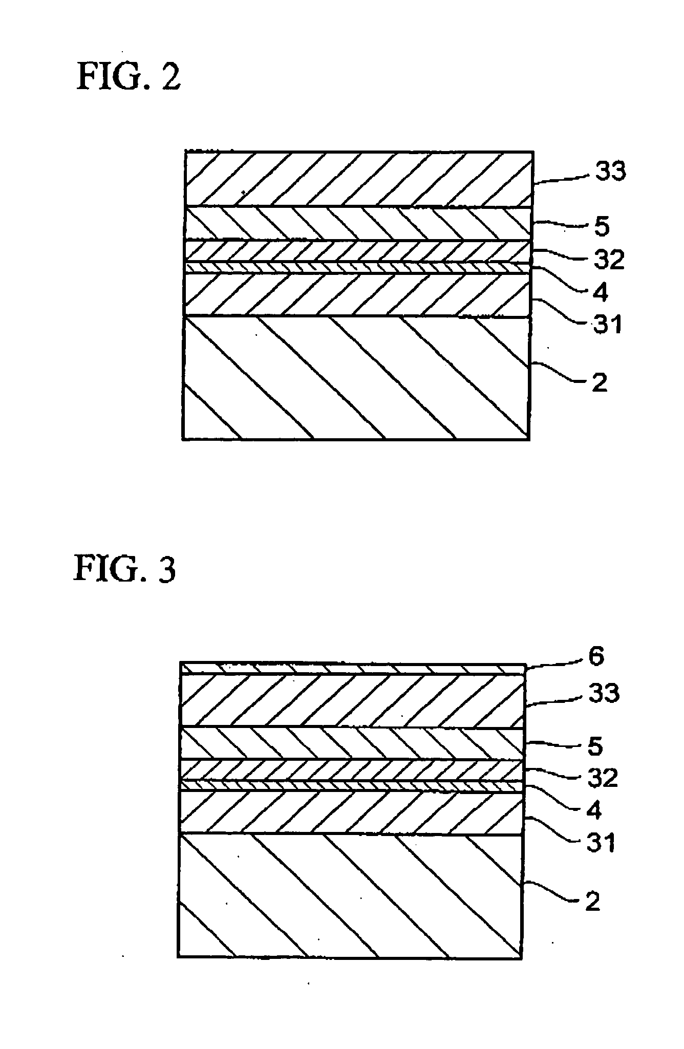
[0118] As shown in FIG. 2, an optical recording disc sample having a multi-layered structure of a substrate 2, a first dielectric layer 31, a noble metal oxide layer 4, a second dielectric layer 32, a light absorption layer 5 and a third dielectric layer was fabricated. More specifically, a polycarbonate substrate (0.6 mm), a ZnS—SiO2 layer (130 nm), a ZnS—SiO2 layer (40 nm), an Ag—In—Sb—Te layer (60 nm) and a ZnS—SiO2 layer (100 nm) were formed, wherein thicknesses are shown in the parentheses. Each of the ZnS—SiO2 layers was formed by the sputtering process using a target having a composition represented by a mole ratio of (ZnS)85(SiO2)15 in an atmosphere of an Ar gas. The AgOx layer was formed by the sputtering process using an Ag target in an atmosphere of a mixed gas of Ar flowing at a flow rate of 10 sccm and O2 flowing at a flow rate of 10 sccm. The value x of the...
working example 1-2
The Optical Recording Medium Having the Structure Shown in FIG. 2 and the Noble Metal Oxide Layer Containing PtOy
[0128] A sample was fabricated in the same manner as that in Working Example 1-1 except that the noble metal oxide layer 4 having a thickness of 4 nm was formed of PtOy. The PtOy layer was formed by the sputtering process using an Pt target in an atmosphere of a mixed gas of Ar flowing at a flow rate of 5 sccm and O2 flowing at a flow rate of 5 sccm. The value y of the thus formed PtOy was equal to 2.
[0129] Recording mark trains whose pitches were 160 nm to 1.6 pin (mark lengths were 80 to 800 nm) were recorded in the sample using the laser beam whose recording power was set to 14 mW. Then, the thus recording mark trains were reproduced using the low resolution pick up and the laser beam whose readout power was set to 1 mW or 4 mW. The results of the reproduction of data are shown in FIG. 7.
[0130] In FIG. 7, in the case where the readout power Pr was 1 mW, when the mar...
PUM
| Property | Measurement | Unit |
|---|---|---|
| Length | aaaaa | aaaaa |
| Wavelength | aaaaa | aaaaa |
| Light | aaaaa | aaaaa |
Abstract
Description
Claims
Application Information