Shield material

a shield material and material technology, applied in the field of shield materials, can solve the problems of deterioration of radiation shielding performance, material density reduction, poor availability as shield material, etc., and achieve the effect of enhancing resistance against breakage and cracks

Inactive Publication Date: 2006-11-09
NIPPON TUNGSTEN CORP
View PDF7 Cites 31 Cited by
  • Summary
  • Abstract
  • Description
  • Claims
  • Application Information

AI Technical Summary

Benefits of technology

[0022] The shielding element integrated with the reinforcing member can be applied to the aforementioned wrapping with the cloth-like sheet to provide enhanced resistance against breakage and cracks during transportation or storage in a folded manner.

Problems solved by technology

At the same time, the lead and lead alloys involves a problem about poor availability as a shield material for use in an area to be subjected to plasticity working, when the lead or lead alloy-based material has a large thickness, because of its hardly shaping ability during a deformation process.
While the use of lead wools can facilitate deformation and shaping, the material becomes more reduced in density along with increase in the degree of deformation and causes a problem about deterioration in radiation-shielding performance.
Moreover, lead itself is harmful to humans, and the use of lead has been increasingly restricted.
However, these materials have difficulties in being shaped through a deformation process, and the resin-based material containing the radiation-shielding powder kneaded thereinto has another disadvantage about fragility and the need for paying particular attention to its handling.
However, the fact of the matter is that the composite material consisting of the metal and organic material is liable to suffer breakage or cracks during handling and thereby required to pay particular attention to its handling as heretofore.
While the strength or content of the organic material may be increased as measures against this problem, such measures will spoil its original flexibility and density, and lead to deterioration in radiation-shielding performance.
Moreover, the composite material consisting of the metal and organic material disadvantageously catches fire easily in the event of a fire or abnormal overheating.

Method used


Image

  • Shield material
  • Shield material
  • Shield material

Examples


example 1

[0029] Table 1 shows various examples where a shield material of the present invention is applied to a nuclear radiation shield.

[0030] In Table 1, samples Nos. 1 to 8 are Inventive Examples, and samples Nos. 9 to 13 are Comparative Examples. Table 1 also shows evaluation results of flexibility, shielding ability, flame resistance, environmental impact and handling performance of each sample, and a comprehensive evaluation thereof.

[0031] As dispersed particles for providing a nuclear radiation-shielding ability, a tungsten powder, a molybdenum powder and a hafnium oxide each having a particle size of about 0.5 to 100 μm were prepared. Further, as an organic material, an olefin elastomer, a vulcanized rubber, a styrene elastomer, an isoprene elastomer and a polyester elastomer were prepared. Then, each of the organic materials was mixed with each of the dispersed particles at a ratio of about 40 volume %, and the mixture was kneaded to obtain a composite material. The obtained compo...

example 2

[0037] Table 2 shows various examples where a shield material of the present invention is applied to an electromagnetic radiation shield.

[0038] In Table 2, examples Nos. 21 to 23 are Inventive Examples. As an electromagnetic radiation-shielding dispersed material, an iron oxide powder and an iron powder were selected. Further, as an organic material, a vulcanized rubber and an olefin elastomer were selected. Then, each of the organic materials was mixed with each of the dispersed materials at a ratio about 40 volume % to form a composite material, and the composite material was treated in the same manner as that in Example 1 to prepare a plate-shaped member of 1 mm×1000 mm×1000 mm.

[0039] As a cloth-like sheet, a VC-coated glass cloth sheet was selected, and two of the glass cloth sheets are prepared. Then, the plate-shaped sheet made of the composite material was sandwiched between the glass cloth sheets, and the outer periphery of the glass cloth sheets was integrally joined to t...

example 3

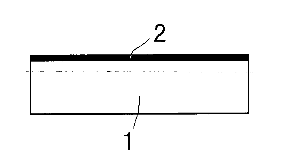
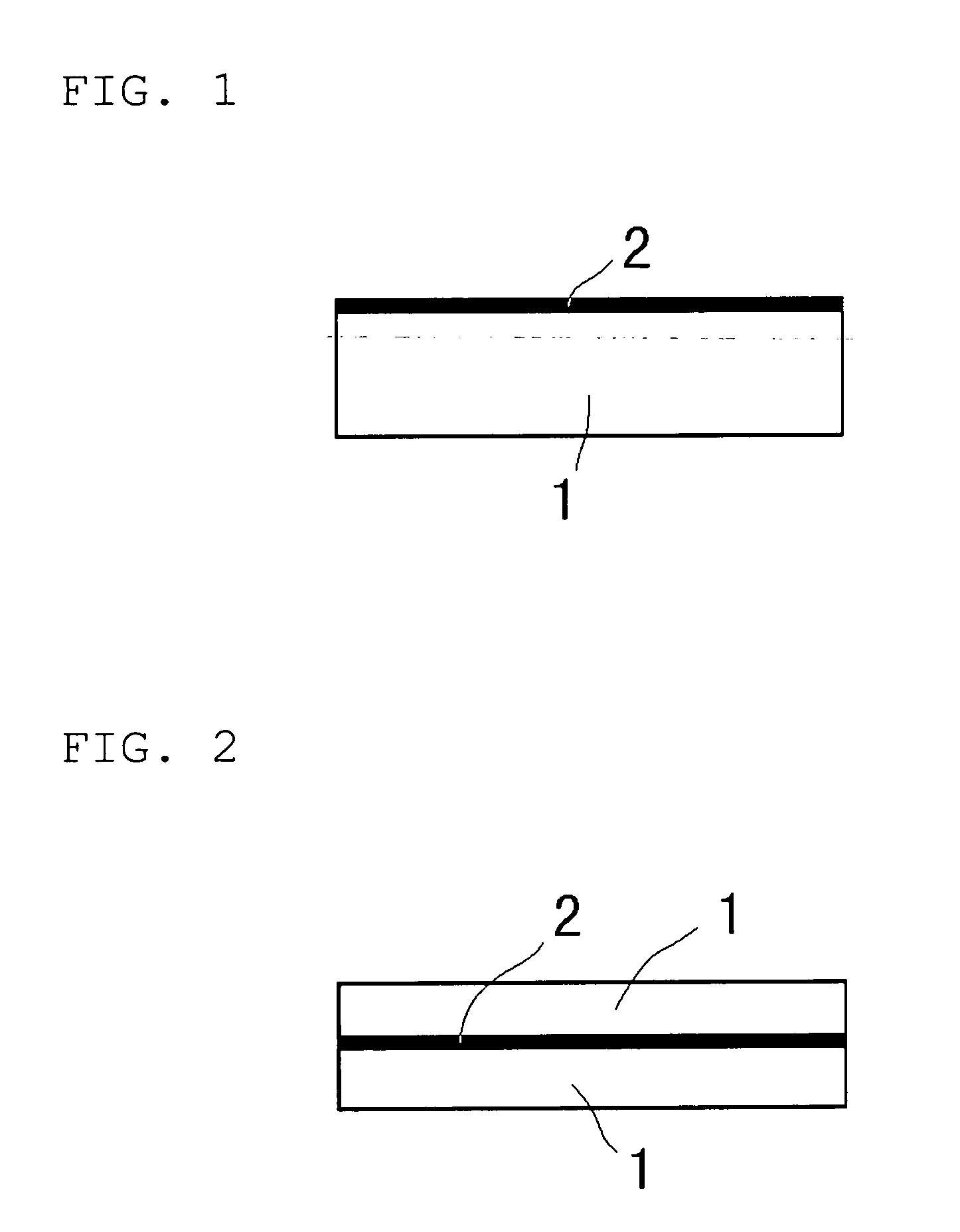
[0044] FIGS. 1 to 5 show various examples of a shield material with a reinforcing member of the present invention.

[0045] When a shielding element 1 comprises a mixture of particles having a radiation shielding ability and a flexible polymer compound, it additionally includes a reinforcing member 2 integrally attached thereto. The reinforcing member 2 may be attached to the shielding element 1 in the following manners. As shown in FIG. 1, when the reinforcement member 2 has a film shape or a mesh shape, it may be attached onto one surface of the shielding element 1. Alternatively, as shown in FIG. 2, the reinforcement member 2 may be embedded in the inside of the shielding element 1.

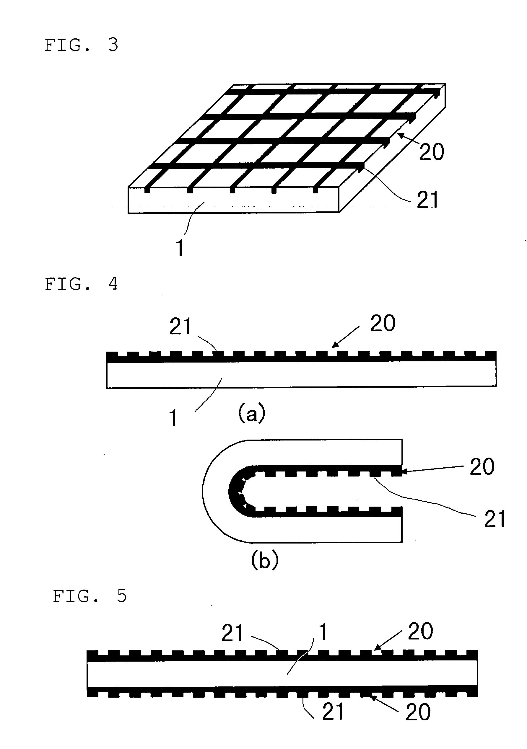
[0046] Further, as shown in FIG. 3, when a reinforcement member 20 has a plurality of protrusions 21 formed on one surface thereof, it may be arranged to allow the protrusions 21 to face downward, and then integrally embedded in the vicinity of one surface of the shielding element 1.

[0047] Further, in ...


PUM

PropertyMeasurementUnit
particle sizeaaaaaaaaaa
temperatureaaaaaaaaaa
thicknessaaaaaaaaaa

Abstract

Disclosed is a fire-resistant lead-free shield material having high shielding ability against nuclear or electromagnetic radiation, and excellent bending workability and handling performance. The shield material comprises a composite material consisting of an organic material and a metal or metal compound having a nuclear or electromagnetic radiation-shielding ability. The composite material is formed into a given shape, such as a plate shape, and wrapped with a cloth-like sheet formed of glass fibers, metal fibers or carbon fibers. Alternatively, the shield material comprises a shielding element consisting of an elastic polymeric organic compound and a particle having a nuclear or electromagnetic radiation-shielding ability, such a heavy metal or ferrite. The shield material also includes either one of a film made of polyethylene, nylon, polyester or metal, a wire mesh formed of nylon fiber or metal fiber, and a plate- or rod-shaped member having a surface formed with a protrusion, which is compression-bonded onto or in the vicinity of a surface of the shielding element, or inside the shielding element.

Description

TECHNICAL FIELD [0001] The present invention relates to a shield material for use as a shield against nuclear or electromagnetic radiation. BACKGROUND ART [0002] Heretofore, lead and lead alloys have been used as a material for a nuclear radiation shield, in terms of high density and excellent radiation-shielding ability. At the same time, the lead and lead alloys involves a problem about poor availability as a shield material for use in an area to be subjected to plasticity working, when the lead or lead alloy-based material has a large thickness, because of its hardly shaping ability during a deformation process. Recent years, an aggregate of thin fibrous lead strands, so-called lead wools, has been increasingly used as a lead-based shield material being capable of shaping. While the use of lead wools can facilitate deformation and shaping, the material becomes more reduced in density along with increase in the degree of deformation and causes a problem about deterioration in radi...

Claims


Application Information

Patent Timeline
Patent Type & Authority Applications(United States)
IPC IPC(8): G21C9/00B32B15/04B32B15/14G21F1/10G21F1/12H05K9/00
CPCB32B15/04B32B15/14G21F1/106G21F1/125G21Y2002/104H05K9/0003G21Y2002/304G21Y2004/10G21Y2004/30G21Y2004/40H05K9/0001G21Y2002/201B32B27/18B32B2262/0261B32B27/12B32B2262/105B32B2262/103B32B2262/106B32B2262/101B32B2307/212B32B3/30B32B2305/72B32B25/10
Inventor OKAMURA, KENJIYAMAUCHI, MASAHIROMATSUO, SHIGERUSAKAGUCHI, SHIGEYA
Owner NIPPON TUNGSTEN CORP
Why Eureka
Try Eureka