Integrated NGL recovery and liquefied natural gas production

a technology of liquefied natural gas and ngl, which is applied in the field of methane separation, can solve the problems of not being able to provide reflux derived from both ngl fractionation and partially condensed scrub column overhead, and the difficulty of recovering heavy hydrocarbons by the scrub column becomes more difficult, so as to maximize the benefit and improve the separation effect of ethane and propan

Inactive Publication Date: 2006-11-23
AIR PROD & CHEM INC
View PDF16 Cites 80 Cited by
  • Summary
  • Abstract
  • Description
  • Claims
  • Application Information

AI Technical Summary

Benefits of technology

[0026] In a preferred embodiment of this invention, the ethane-enriched stream, preferably deethanizer overhead, obtained from NGL fractionation is condensed, pumped, combined with the reflux stream obtained by partially condensing the scrub column overhead vapor and recycled to the scrub column, preferably to a scrub column reflux drum. This allows the scrub column to operate at a higher pressure by increasing the mixture's critical pressure and also improves ethane-propane separation. The ethane-enriched stream can be fully condensed using mixed refrigerant (MR) refrigeration available in the main heat exchanger of the LNG process to maximize the benefit.

Problems solved by technology

However, recovery of heavy hydrocarbons by the scrub column becomes more difficult with increasing pressure and it is not possible to separate a mixture at a pressure above its critical pressure.
In options (i), (iii) and (iv), additional reflux to the scrub column can be provided by condensing a slipstream of the feed gas portion but there is no teaching of providing reflux derived from both NGL fractionation and partially condensed scrub column overhead.
None of these patents show reflux obtained by partially condensing the overhead product.

Method used


Image

  • Integrated NGL recovery and liquefied natural gas production
  • Integrated NGL recovery and liquefied natural gas production
  • Integrated NGL recovery and liquefied natural gas production

Examples


example

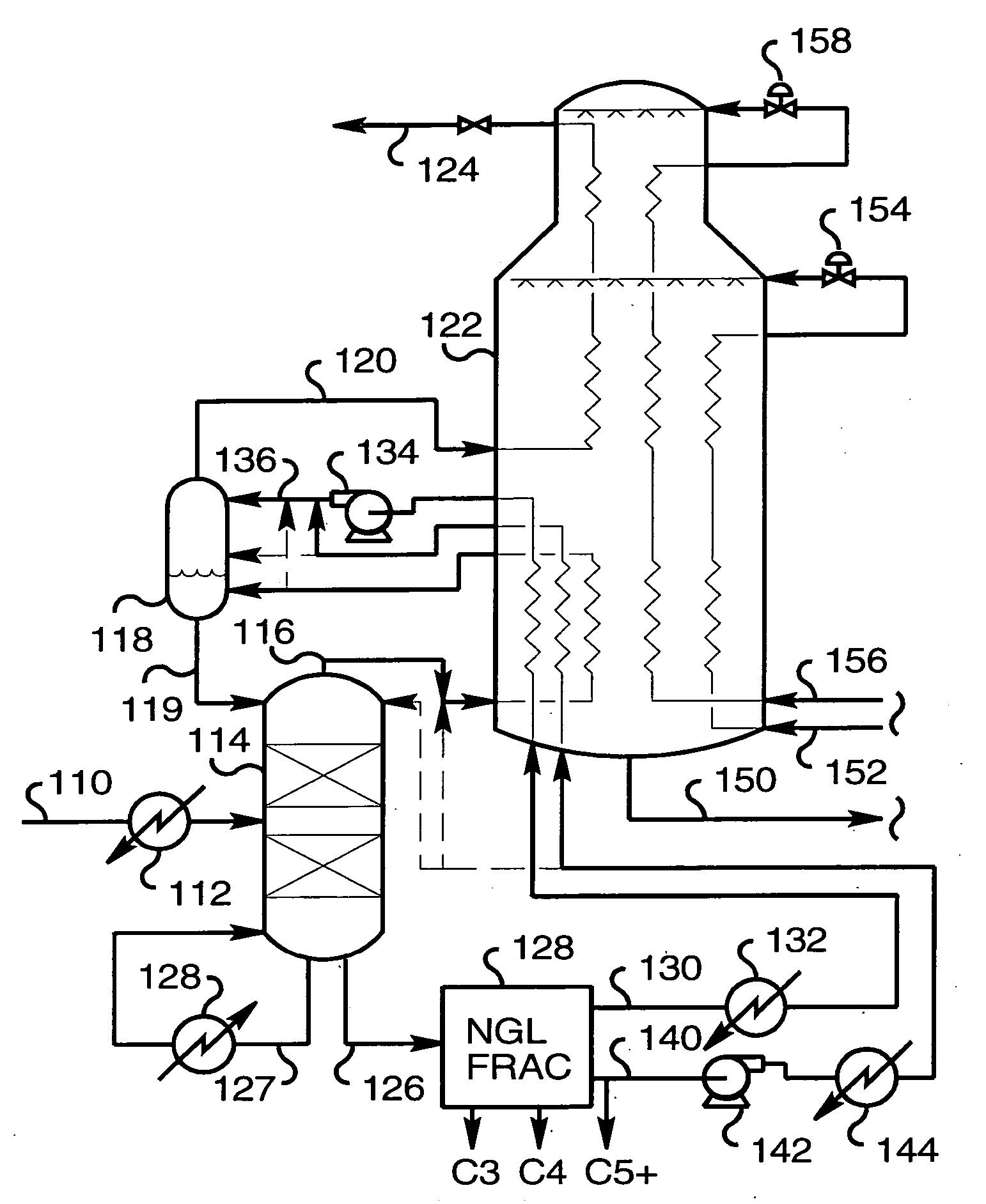
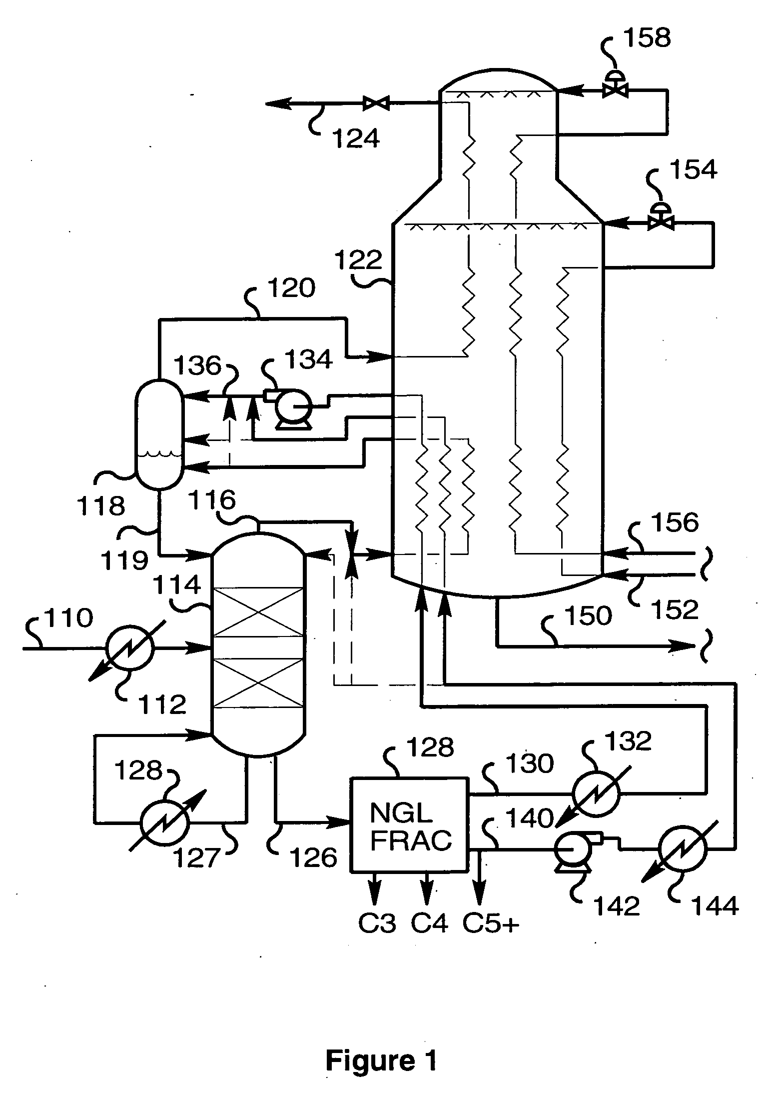
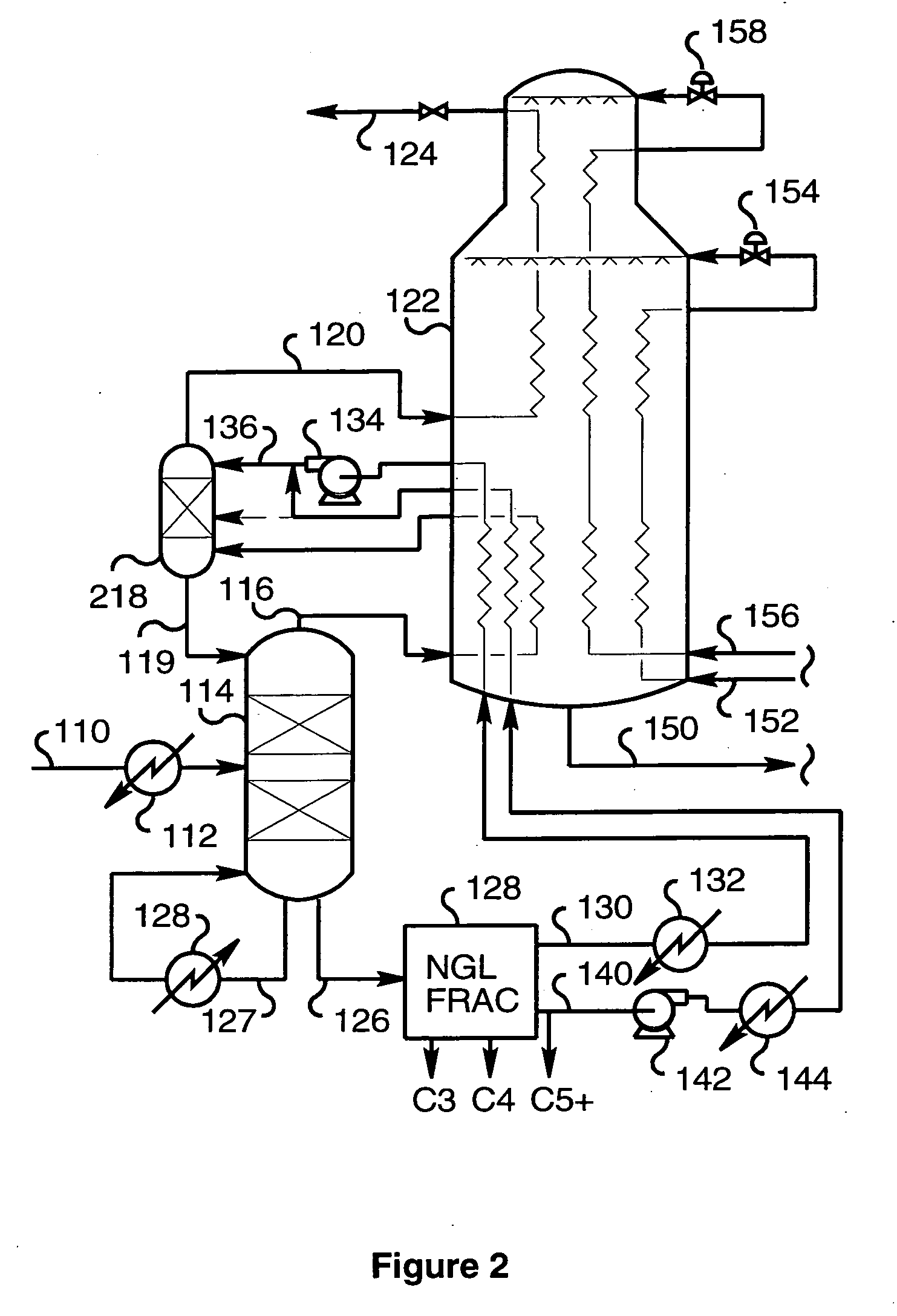
[0125] Using the embodiment of FIG. 3, 97,904 lbmol / h (44,408.5 kgmol / h) of a pre-purified natural gas stream 110 at 950 psia (6.5 MPa) is cooled in heat exchanger 112 by three stages of propane cooling to −32.3° F. (−35.7° C.) and fed to the scrub column 114. This feed stream 110 contains 0.6% nitrogen, 84.8% methane, 7.3% ethane, 4.4% propane, 0.7% isobutane, 1.5% butane, 0.3% isopentane, 0.2% pentane, and 0.2% hexanes. The column 114 operates at 840 psia (5.8 MPa) and has an intermediate reboiler heated by 40% of the stream 110 bypassing the first two stages of propane cooling and a bottom reboiler 128 at about 130° F. (55° C.). Column overhead 116 is cooled from −62.3° F. (−52.4° C.) to −77.5° F. (−60.8° C.) in the warm bundle of the main heat exchanger 122 and introduced into the reflux drum 118 as a two-phase stream containing about 15% of liquid. Scrub column bottoms stream 126 is sent to the fractionation systems 128, consisting of a series of distillation columns comprising...


PUM


Abstract

The separation of methane from an admixture (110) with ethane and higher hydrocarbons, especially natural gas, using a scrub column (114), in which the admixture is separated into a methane-rich overhead (116) that is partially condensed (122) to provide reflux to the column (114) and liquid methane-depleted bottoms liquid (126), is improved by providing additional reflux (136) derived from an ethane enriched stream (130) from fractionation (128) of the bottoms liquid. Preferably, absorber liquid (140) from the fractionation (128) also is introduced into the scrub column. The vapor fraction (120) remaining after partial condensation can be liquefied (122) to provide LNG product (124).

Description

BACKGROUND OF THE INVENTION [0001] The present invention relates to the separation of methane from admixture with ethane and heavier hydrocarbons and has particular, but not exclusive, application to an integrated process in which natural gas liquids (NGL) are recovered and liquefied natural gas (LNG) produced from natural gas (NG). [0002] Natural gas comprises primarily methane and minor constituents that include heavier hydrocarbons. Liquefied natural gas contains mostly methane. The hydrocarbons heavier than methane are usually condensed and recovered as natural gas liquids and fractionated to yield valuable hydrocarbon products. [0003] A typical NG liquefaction system comprises a scrub column fed with raw natural gas or pipeline gas and producing a methane-rich overhead vapor and NGL as bottoms liquid. A portion of methane-rich overhead vapor is partially condensed to provide reflux for the column and the remainder liquefied to provide the LNG product. The bottoms liquid is frac...

Claims


Application Information

Patent Timeline
Patent Type & Authority Applications(United States)
IPC IPC(8): F25J3/00
CPCF25J1/0022F25J2290/40F25J1/0055F25J1/0216F25J1/0231F25J1/0239F25J1/0241F25J1/0258F25J1/0292F25J3/0209F25J3/0233F25J3/0242F25J2200/02F25J2200/30F25J2200/74F25J2205/02F25J2205/50F25J2215/64F25J2235/60F25J2245/02F25J2270/12F25J2270/60F25J2270/66F25J1/0052F25J1/0214F25J2205/30F25J3/02F25J1/02
Inventor ROBERTS, MARK JULIANBROSTOW, ADAM ADRIAN
Owner AIR PROD & CHEM INC
Why Eureka
Try Eureka