Method of fabricating a semiconductor device

a semiconductor device and manufacturing method technology, applied in the direction of semiconductor devices, basic electric elements, electrical appliances, etc., can solve the problems of increasing the leakage current of a plurality of transistors in the cell region, the overall process of fabricating the semiconductor device may become complicated, and the fabrication cost may increase undesirably, so as to reduce the number of processing steps, simplify the overall process of fabricating the semiconductor device, and minimize the misalignment of the impurity regions

Inactive Publication Date: 2006-11-23
SAMSUNG ELECTRONICS CO LTD
View PDF5 Cites 30 Cited by
  • Summary
  • Abstract
  • Description
  • Claims
  • Application Information

AI Technical Summary

Benefits of technology

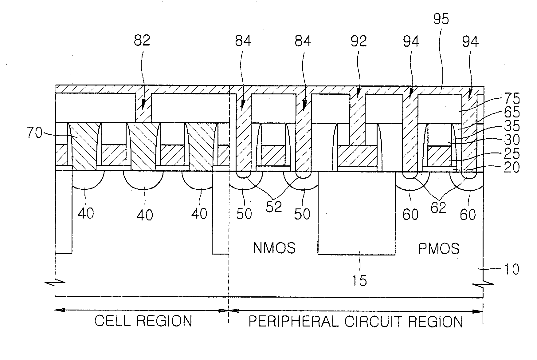
[0021] According to some embodiments of the present invention, an overall semiconductor fabrication process can be simplified by reducing the number of processing steps for forming ion implantation masks and the variation of the characteristics of a plurality of transistors due to a plug effect can be minimized.
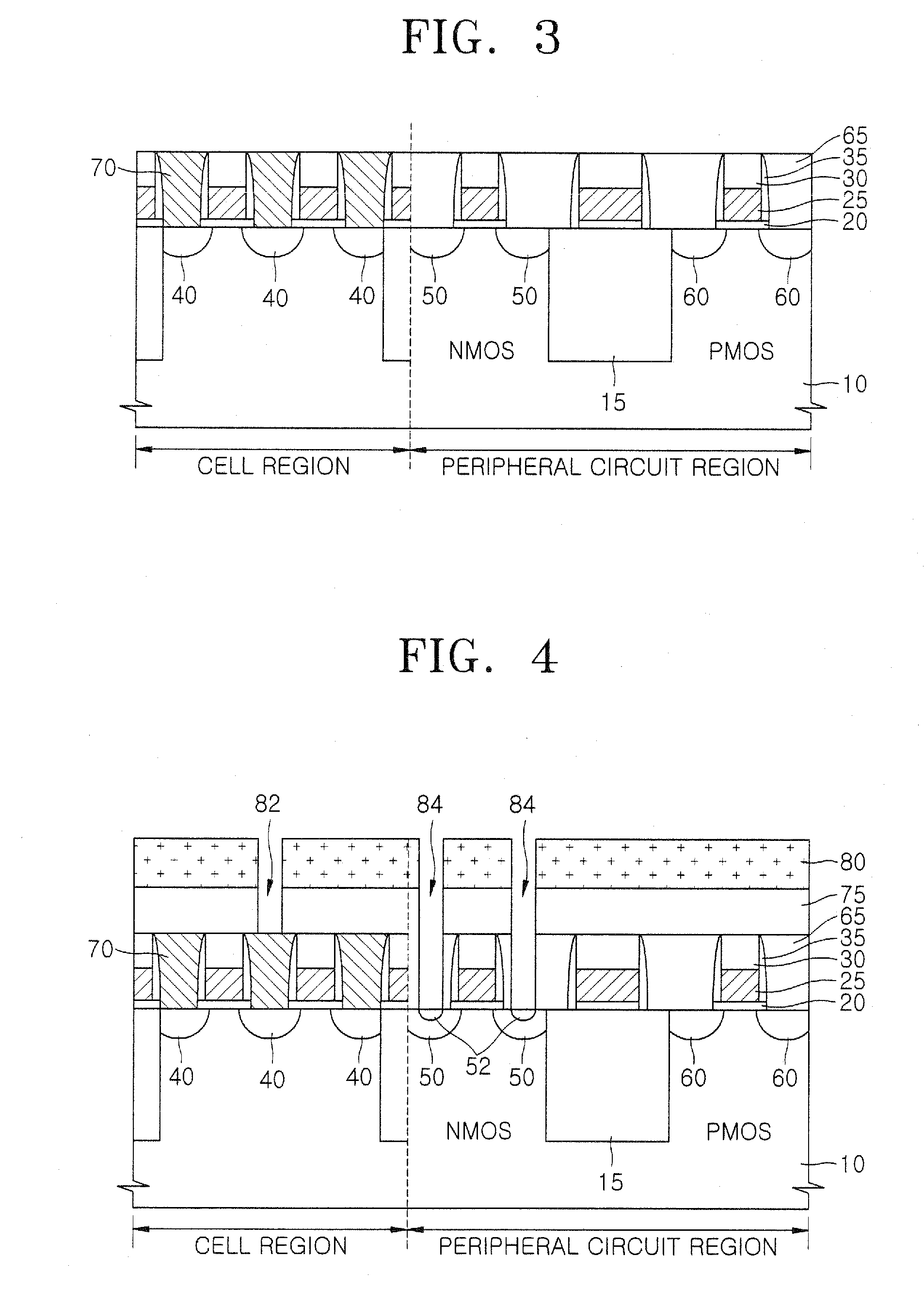
[0023] In this method, the source / drain regions are formed after the interlayer insulation layer is formed. Thus, the profiles of the source / drain regions can be prevented from being adversely affected by the heat budget even when the interlayer insulation layer is formed of BPSG and a reflowing process is performed on the interlayer insulation layer at high temperatures.
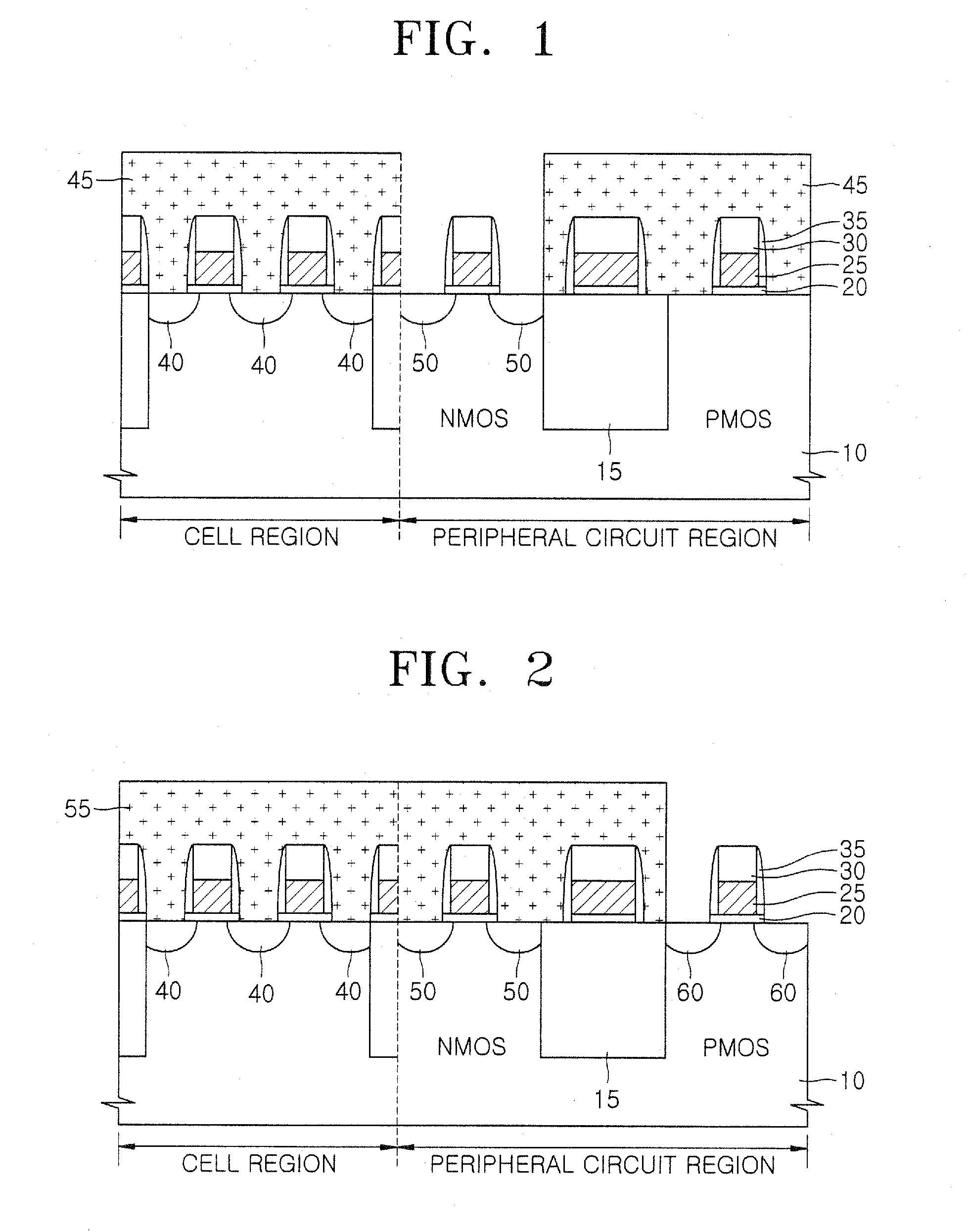
[0026] The method may also include forming a high-concentration N+ impurity region in each of the N-type source / drain regions by implanting a high concentration of N+ ions into the semiconductor substrate through the first contact holes, after the forming of the N-type source / drain regions. Accordingly, it is possible to simplify the overall process of fabricating a semiconductor device by reducing the number of times a process of forming a photoresist pattern, which would be used as an ion implantation mask, is performed. In the forming of the first contact holes, the forming of the N-type source / drain regions, and the forming of the high-concentration N+ impurity region, the same photoresist pattern is used.
[0028] In the forming of the second contact holes, the forming of the P-type source / drain regions, and the forming of the high-concentration P+ impurity region, the same photoresist pattern may be used. Accordingly, it is possible to reduce the variation of the characteristics of a plurality of transistors in the peripheral circuit region due to the misalignment of impurity regions by etching the interlayer insulation layer in the area-type manner to form the source / drain regions and the high concentration impurity regions.
[0030] In this method, the source / drain regions in the peripheral circuit region are formed after the first and second interlayer insulation layers and the landing pad are formed. Therefore, the profiles of the source / drain regions can be prevented from being adversely affected by heat budget in a reflowing process performed on the first and second interlayer insulation layers and in an annealing process performed on the landing pad. In addition, the formation of the source / drain regions and the formation of the high concentration impurity regions can be combined. As a result, the overall process of fabricating a semiconductor device can be simplified by reducing the number of processing steps for forming a photoresist pattern as an ion implantation mask. Moreover, since the first and second interlayer insulation layers are etched in the area-type manner to form the source / drain regions and the high concentration impurity regions, the variation of the characteristics of a plurality of transistors in the peripheral circuit region due to the misalignment of the impurity regions can be minimized.

Problems solved by technology

However, when the etching process for forming a contact hole in the cell region and the etching process for forming a contact hole in the peripheral circuit region are performed separately from each other, an overall process of fabricating the semiconductor device may become complicated and the fabrication costs may undesirably increase because of the need to form photoresist patterns used for forming a bitline contact in the cell region and in the peripheral circuit region.
However, the first and second interlayer insulation layers 65 and 75 may not be able to be sufficiently planarized when reflowed at low temperatures, and the landing pad 70 may increase leakage current of a plurality of transistors in the cell region when annealed at low temperatures.
Accordingly, five different processing steps of forming 5 photoresist patterns are needed, which makes the overall semiconductor fabrication process complicated and increases overall manufacturing costs.
Accordingly, the transistor may suffer any number of problems such as a plug effect, due to misalignment of the impurity regions.

Method used


Image

  • Method of fabricating a semiconductor device
  • Method of fabricating a semiconductor device
  • Method of fabricating a semiconductor device

Examples


Embodiment Construction

[0034] The present invention will now be described more fully with reference to the accompanying drawings in which exemplary embodiments of the invention are shown. This invention may, however, be embodied in many different forms and should not be construed as being limited to the embodiment set forth herein. Rather, this embodiment is provided so that this disclosure will be thorough and complete, and will fully convey the scope of the invention to those skilled in the art. In the drawings, the forms of elements are exaggerated for clarity. To facilitate understanding, identical reference numerals have been used, where possible, to designate identical elements that are common to the figures.

[0035]FIGS. 8 through 13 are cross-sectional views illustrating a method of fabricating a semiconductor device according to an exemplary embodiment of the present invention.

[0036] Referring to FIG. 8, a device isolation layer 215, such as shallow trench isolation (STI), is formed on a semicond...


PUM


Abstract

A method of fabricating a semiconductor device to prevent the profiles of source / drain regions from being deformed due to the thermal budget. The method can simplify the overall process of fabricating a semiconductor device by reducing the number of processing steps of forming a photoresist pattern as an ion implantation mask, and can reduce the variations of the transistor characteristics.

Description

CROSS-REFERENCE TO RELATED PATENT APPLICATION [0001] This application claims the benefit of Korean Patent Application No. 10-2005-0042456, filed on May 20, 2005, in the Korean Intellectual Property Office, the disclosure of which is incorporated herein in its entirety by reference. BACKGROUND OF THE INVENTION [0002] 1. Field of the Invention [0003] The present invention relates to a method of fabricating a semiconductor device, and more particularly, to a method of fabricating a semiconductor device having bitline contact plugs and bitlines. [0004] 2. Description of the Related Art [0005] As patterns used to fabricate semiconductor devices become more sophisticated, an increasing number of these semiconductor devices are manufactured by forming a contact in a cell region of a semiconductor substrate and forming a contact in a peripheral circuit region of the semiconductor substrate in separate processes dealing with different etching targets. In other words, in the cell region, a co...

Claims


Application Information

Patent Timeline
Patent Type & Authority Applications(United States)
IPC IPC(8): H01L21/8234
CPCH01L21/823814H01L27/10894H01L27/10888H01L21/823878H10B12/485H10B12/09H01L21/28
Inventor KANG, NAM-JUNGKIM, JI-YOUNG
Owner SAMSUNG ELECTRONICS CO LTD
Why Eureka
Try Eureka