Light emitting apparatus and method of manufacturing the same

a technology manufacturing method, which is applied in the direction of electrical apparatus, semiconductor/solid-state device manufacturing, semiconductor devices, etc., can solve the problems of reducing the reliability of light emitting apparatus, deterioration or discoloration of molding resin, and difficulty in making light emitting apparatus having sufficient reliability, so as to improve the efficiency of wavelength conversion, improve workability, and minimize color unevenness with the direction

Active Publication Date: 2006-11-30
NICHIA CORP
View PDF32 Cites 166 Cited by
  • Summary
  • Abstract
  • Description
  • Claims
  • Application Information

AI Technical Summary

Benefits of technology

[0009] Therefore, an object of the present invention is to provide a light emitting apparatus having a high reliability that uses a light emitting device that emits light including wavelength shorter than that of blue light and a fluorescent substance, and a method of manufacturing the same.
[0065] With the method of manufacturing the light emitting apparatus according to the present invention, since the fluorescent substance is deposited on the package whereon a plurality of light emitting devices are arranged, it is made possible to simultaneously manufacture a large number of light emitting apparatuses satisfactorily. Even when the quantity of the fluorescent substance deposited on the light emitting device is very small, quantity of the fluorescent substance (namely thickness of the coating layer) can be controlled to be uniform. As a result, light emitting apparatuses having less variability can be manufactured.

Problems solved by technology

However, the white light emitting apparatus of the prior art uses the resin containing a fluorescent substance, and the molding resin is subjected to deterioration or discoloration when light of short wavelength is used or high optical power output that accompanies significant heat generation is employed.
Therefore, the bonding resin is subjected to deterioration that results in a decrease in the bonding strength when light of short wavelength is used or high optical power output that accompanies significant heat generation is employed.
As a result, it has been difficult to make a light emitting apparatus having sufficient reliability by using a light emitting device that emits light including wavelength shorter than that of blue light.
The white light emitting apparatus of the prior art also has such a problem that thickness (quantity of the fluorescent substance) of the molding resin serving as a coating layer is different from point to point across the surface of the light emitting apparatus, resulting unevenness in the light intensity from the light emitting device and in the light intensity from the fluorescent substance.

Method used


Image

  • Light emitting apparatus and method of manufacturing the same
  • Light emitting apparatus and method of manufacturing the same
  • Light emitting apparatus and method of manufacturing the same

Examples


embodiment 1

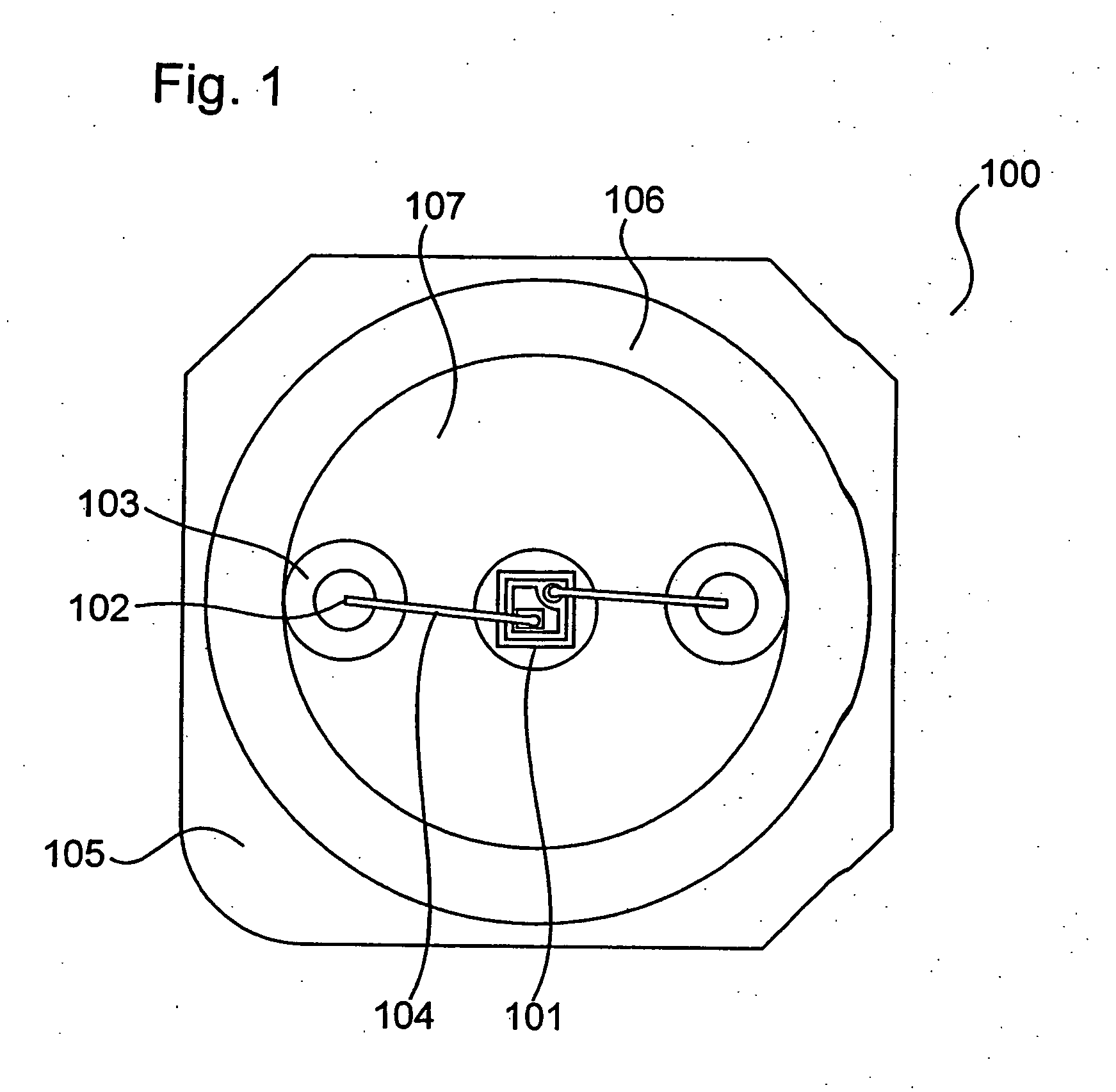
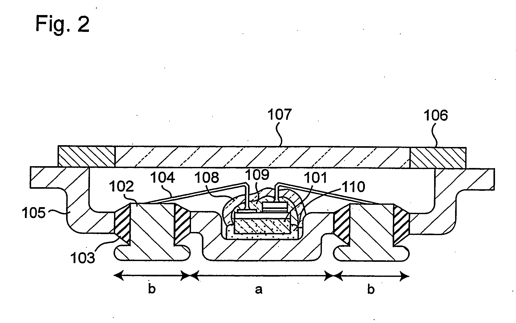
[0077]FIG. 1 and FIG. 2 are top view and sectional view, respectively, showing an example of a light emitting apparatus manufactured according to the method of the present invention.

[0078] In FIG. 1 and FIG. 2, an LED 101 that is a light emitting device is mounted in a metallic package 105. The package 105 has a recess “a” located at the center thereof. A base portion “b” that surrounds the recess “a” has two through holes penetrating in the direction of thickness, the through holes opposing each other across the recess “a”. Positive and negative lead electrodes 102 are inserted through the respective through holes via hard glass 103 that serves as an insulating member. The metal package 105 has a light transmitting window 107 and a lid 106 comprising a metal part provided on the principal surface thereof, so that the light emitting deice and other component are hermetically sealed together with nitrogen gas in the package, by welding the metallic part of the lid 106 and the contac...

embodiment 2

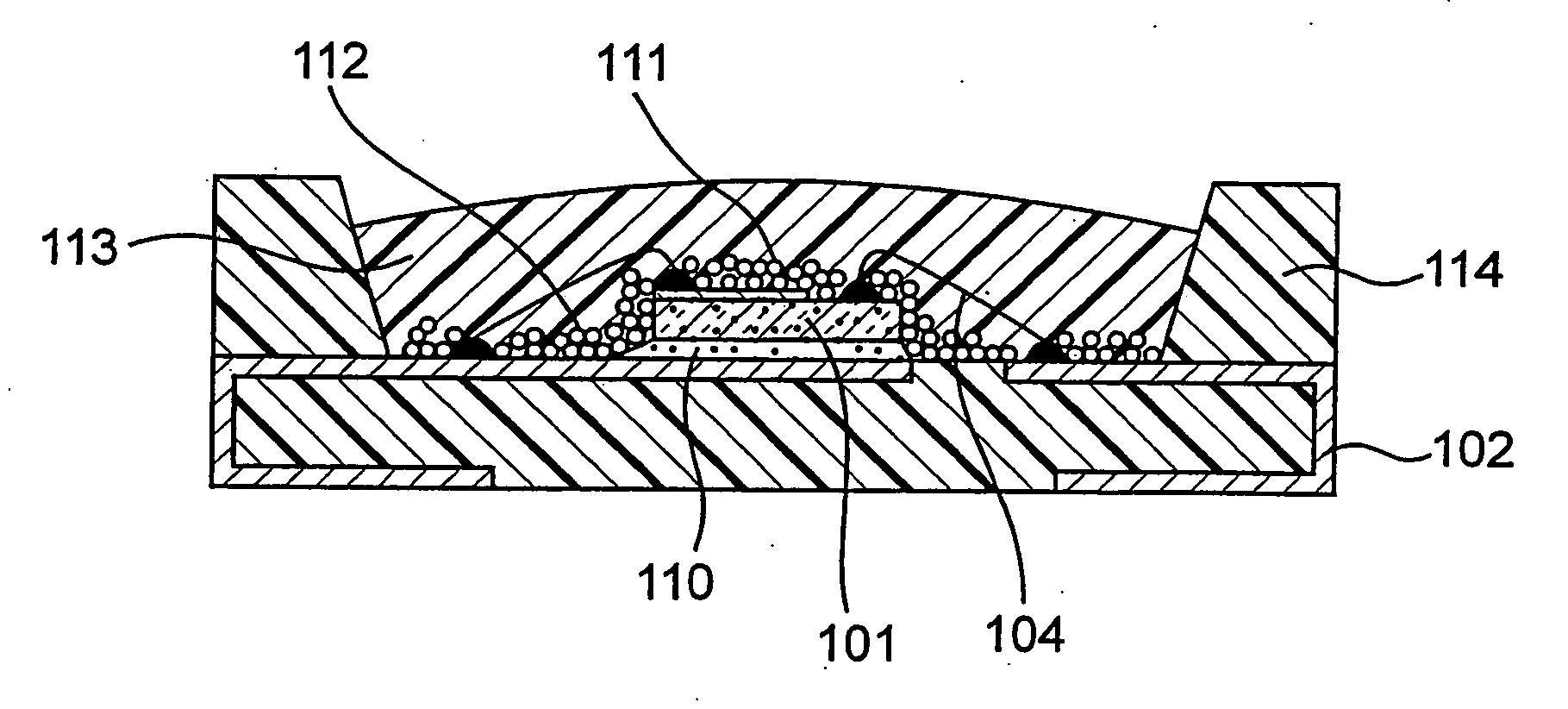
[0192]FIG. 3 is a schematic sectional view showing another embodiment of the light emitting apparatus of the present invention.

[0193] This embodiment is an application of the present invention to an LED mounted on a resin package, unlike the first embodiment. FIG. 3 shows the structure of an LED package 114 that serves as supporting body whereon the LED 101 is mounted. Reference numeral 104 denotes an electrically conductive wire, 113 denotes a molding member, 111 denotes a coating layer provided on the LED chip, 112 denotes a coating layer provided on the supporting body and 110 denotes an adhesive layer. In this embodiment, the coating layers 111 and 112 are single layers of an oxide that consists mainly of SiO2 and contains fluorescent substance. The light emitting device 101 and the coating layers 111 and 112 are sealed with the molding resin 113, unlike in the first embodiment. The LED chip 101 is encased in the package 114, and is bonded onto one of external electrodes via si...

embodiment 3

[0208] This embodiment is a method of spraying the coating solution in the form of spiral stream of mist that contains the fluorescent substance from above the light emitting device that is placed on the supporting body and is being heated. This method can be applied not only to the coating material of the present invention that is made of an inorganic material, but also to a coating material of the prior art that is made of an organic material.

[0209]FIG. 4 is a schematic diagram showing the process of spraying the coating solution to the light emitting device that is fastened onto the supporting body. This embodiment uses an apparatus that discharges the coating solution 203 and a gas (air in this embodiment) in a spiral stream from a nozzle 201. The apparatus has several gas vents disposed around the nozzle 201, while the gas discharged from these vents is directed toward the surface to be coated with a certain angle. As a result, as the gas is supplied through the vents that rot...


PUM


Abstract

A light emitting apparatus comprising a light emitting device (101) disposed on a supporting body (105), and coating layers ((108, 109) that bind a fluorescent substance that absorbs light emitted by the light emitting device (101) and emits light of a different wavelength and secures the fluorescent substance onto the surface of the light emitting device (101). The coating layers (108, 109) are made of an inorganic material including an oxide and a hydroxide, each containing at least one element selected from the group consisting of Si, Al, Ga, Ti, Ge, P, B, Zr, Y, Sn, Pb and alkali earth metals. Also an adhesive layer (110) is made of the same inorganic material as that of the coating layers (108, 109).

Description

TECHNICAL FIELD [0001] The present invention relates to a light emitting apparatus that can be used as light source for illumination, LED display, back light for display, traffic light, light source for illuminating switch, various sensors and indicators and a method of manufacturing the same BACKGROUND ART [0002] Light emitting apparatuses (white light emitting apparatus) capable of emitting white light have been developed and put in practical use in recent years, that combine a light emitting device chip constituted using a gallium nitride-based compound semiconductor and a fluorescent substance. The light emitting apparatus emits blended light of white color by converting the wavelength of part of blue light, that is emitted by the light emitting device, by means of a fluorescent substance and mixing this light having the converted wavelength and the blue light emitted by the light emitting device. [0003] In the prior art, it has been a common practice to manufacture a light emit...

Claims


Application Information

Patent Timeline
Patent Type & Authority Applications(United States)
IPC IPC(8): H01L33/00H01L21/762H01L33/06H01L33/22H01L33/32H01L33/44H01L33/50H01L33/54H01L33/56H01L33/62
CPCH01L21/76251H01L33/32H01L33/44H01L33/483H01L33/501H01L33/62H01L2224/0603H01L2224/45144H01L2224/48227H01L2224/48465H01L2224/73265H01L2924/01004H01L2924/01012H01L2924/01013H01L2924/01014H01L2924/0102H01L2924/01025H01L2924/01029H01L2924/01046H01L2924/01057H01L2924/01063H01L2924/01077H01L2924/01078H01L2924/01079H01L2924/09701H01L2924/3025H01L2224/32225H01L2924/0132H01L24/29H01L2924/01019H01L2924/01021H01L2924/01037H01L2924/01066H01L2924/01067H01L2924/01068H01L2924/01322H01L2924/014H01L2924/0133H01L2924/157H01L2224/29111H01L2924/12041H01L2224/2919H01L2924/01028H01L2224/32257H01L2224/49107H01L2224/8592H01L2924/00014H01L2924/0105H01L2924/00H01L2924/01026H01L2924/01027H01L2924/01042H01L2924/01074H01L2924/01049H01L2924/3512H01L2924/351H01L2924/181H01L2924/12042H01L2924/12036H01L2924/00012
Inventor IZUNO, KUNIHIROMATSUMOTO, KOUKINAGAHAMA, SHINICHISANO, MASAHIKOYANAMOTO, TOMOYASAKAMOTO, KEIJI
Owner NICHIA CORP
Why Eureka
Try Eureka