Electronic control of vehicle air suspension

a technology of electronic control and air suspension, which is applied in the direction of shock absorbers, mechanical equipment, transportation and packaging, etc., can solve the problems of affecting affecting the operation of the vehicle, so as to reduce the amount of mechanical power, prolong the life of the air compressor, and accelerate the filling or dumping of air bags

Inactive Publication Date: 2006-11-30
BARKSDALE
View PDF20 Cites 42 Cited by
  • Summary
  • Abstract
  • Description
  • Claims
  • Application Information

AI Technical Summary

Benefits of technology

[0006] In accordance with one embodiment of the present invention, an apparatus for sensing air bag height is provided for use in a vehicle, which generates an electrical signal for use by an electrically-controlled air valve. The apparatus includes a pair of electronic tilt sensors, one tilt sensor being mounted on the vehicle frame and the other being coupled to a tilt arm extending between the frame and the axle assembly and pivotally coupled to each of them. In most cases where a swing arm extends from the frame to the axle assembly, the swing arm serves as the tilt arm on which one tilt sensor is mounted. Any change in the tilt angle of the two sensors indicates a change in tilt angle of the swing arm with respect to the vehicle frame, which indicates a change in air bag height. The electrical outputs of the tilt sensors are delivered to an electronic control

Problems solved by technology

Some disadvantages of a mechanical linkage are that it is usually thin and easily damaged, and has bushings that wear out.
Also, a repairman may improperly adjust it, causing rapid wear of the vehicle transmission and poor vehicle suspension.
Further, the air control valve may react instantly to road bumps and undulations, or short term vehicle acceleration

Method used


Image

  • Electronic control of vehicle air suspension
  • Electronic control of vehicle air suspension
  • Electronic control of vehicle air suspension

Examples


Embodiment Construction

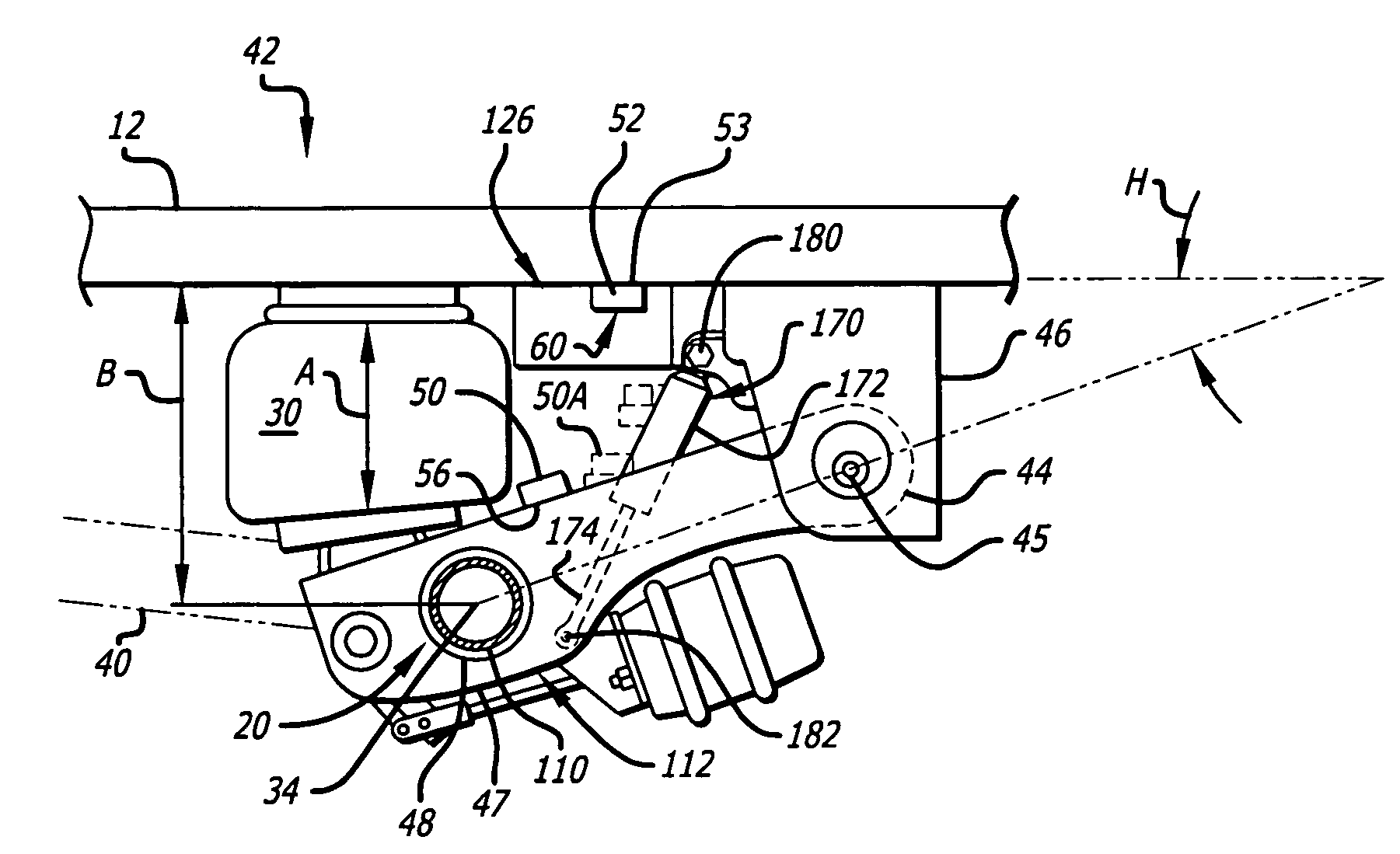
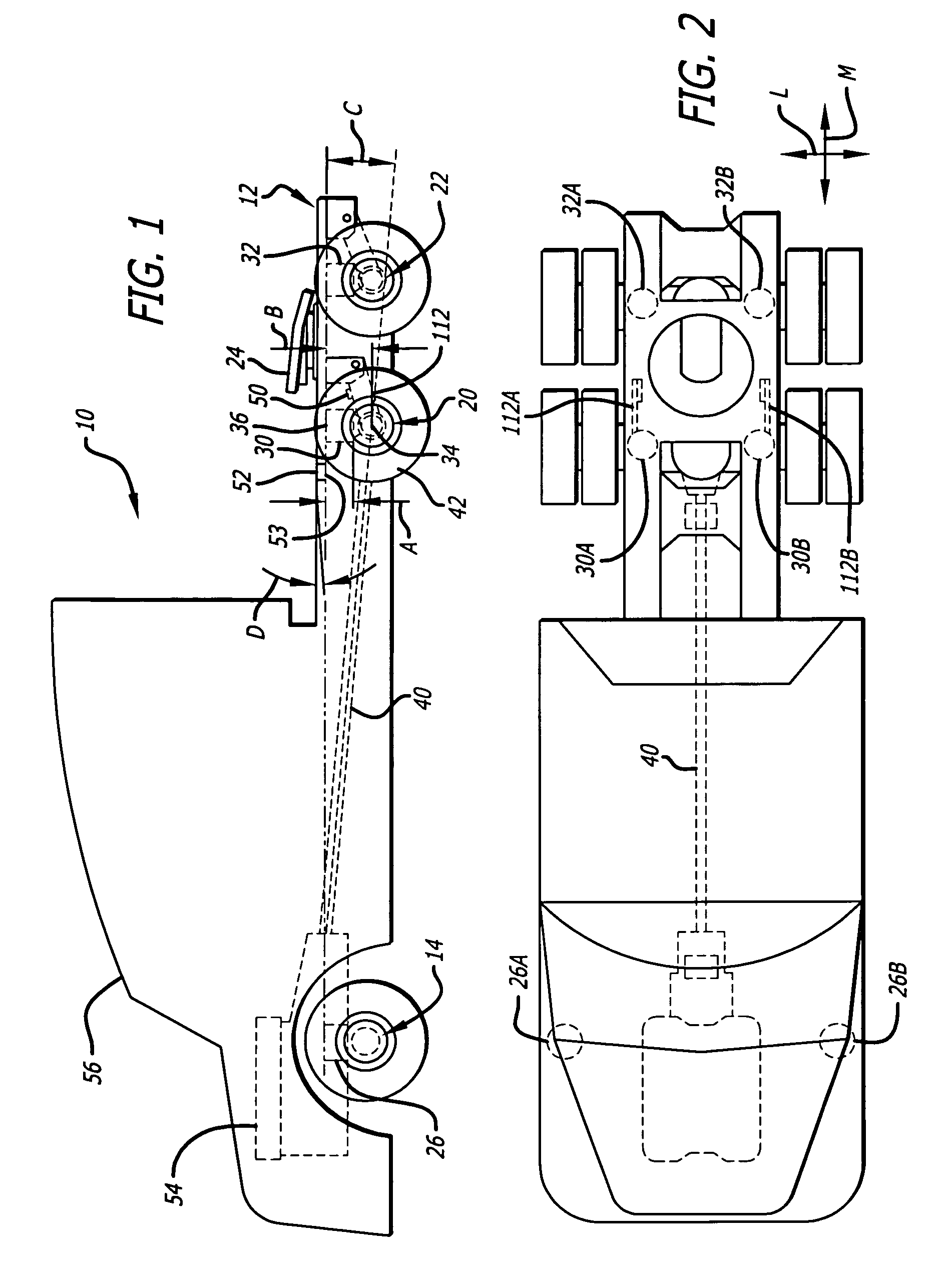
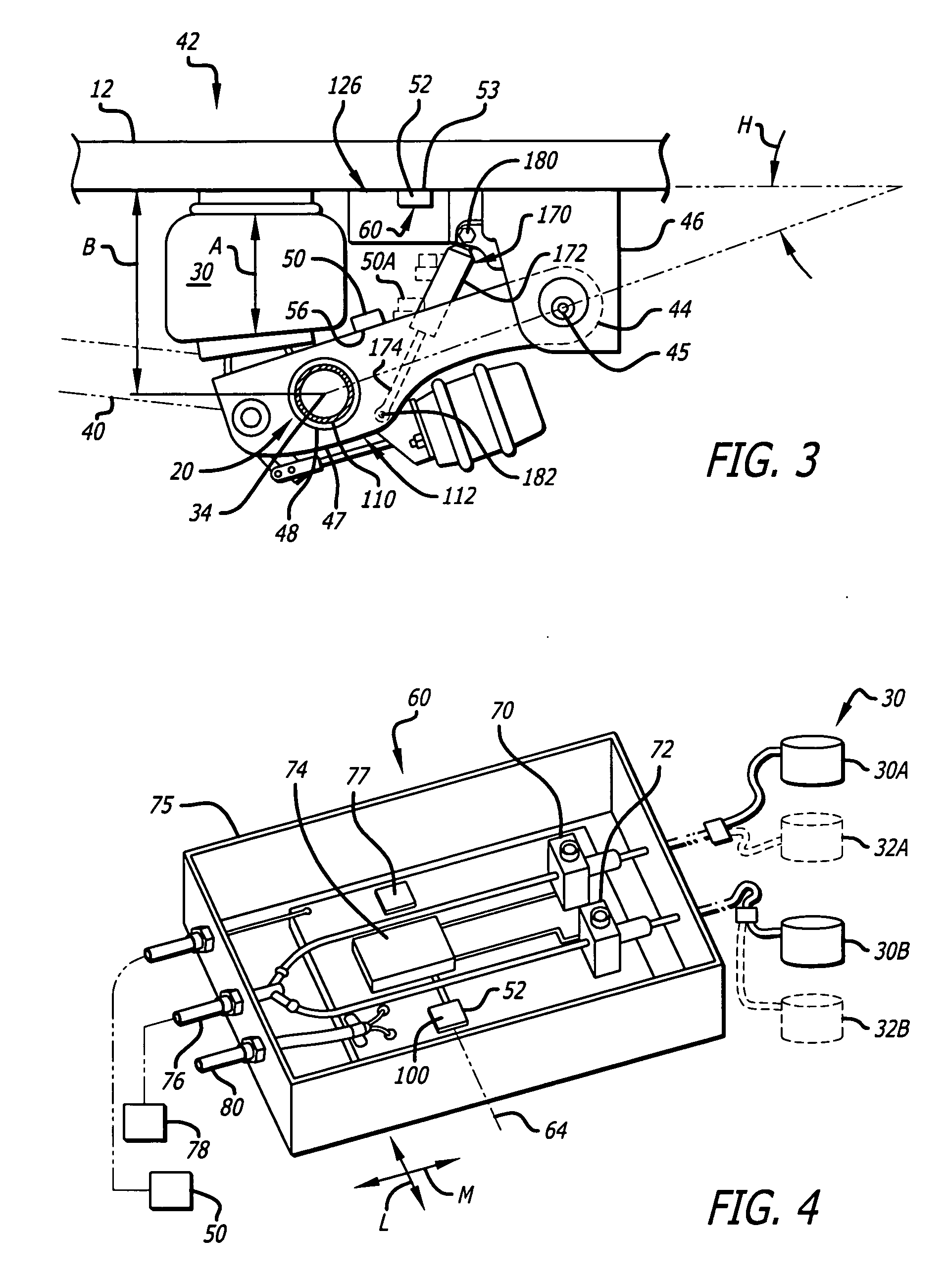
[0019]FIG. 1 illustrates portions of a large vehicle or truck 10, which includes a frame 12, a front axle assembly 14, and two rear axle assemblies 20, 22. Axle assembly 20 is a drive axle assembly whose axle is driven by a drive shaft 40 that is, in turn, driven by an engine 54 at the front of the vehicle. The drive axle assembly 20 includes bearings that rotatably support the drive axle, and can include a differential gear train and housing, etc. The large weight of a trailer is applied to the rear portion 24 of the truck, and the two rear axle assemblies support that weight. Air bags 26, 30, 32 support locations on the frame 12 on the axle assemblies. As mentioned above, the height of each air bag, such as A, is determined by the manufacturer, and when this height is maintained, the axis 34 of the drive axle assembly 20 is maintained at a predetermined ride height B below the frame. A large deviation from the optimum air bag height for air bags 30, 32 for a considerable period of...


PUM


Abstract

A system is provided for use on large vehicles of the type wherein the vehicle frame is supported on vehicle axle assemblies through air bags, and each air bag has a lower end coupled to the lower end of an arm such as a swing arm whose upper end is pivotally mounted on the frame. The height of the air bag is sensed by a pair of tilt sensors, sensing tilt of its location with respect to gravity, and the difference in tilt indicates air bag height. The output of the tilt sensors may be filtered, and a motion detector allows rapid filling or dumping of air bags independent of filtering of tilt sensor signals. Control of the vehicle air suspension can also be based upon inputs from one or more air bag pressure sensors.

Description

CROSS-REFERENCES TO RELATED APPLICATIONS [0001] This application is a continuation-in-part of Ser. No. 11 / 123,728, filed May 6, 2005, which is a continuation of Ser. No. 10 / 355,900, filed Jan. 31, 2003, which is based on provisional application Ser. No. 60 / 375,464, filed Apr. 23, 2002.BACKGROUND OF THE INVENTION [0002] Large vehicles commonly have a frame rear portion supported on a rear axle assembly at least partially through an air bag. Smaller vehicles are also starting to use this type of suspension. In many cases, swing arms are used to control the horizontal position of the frame relative to the rear axle assembly. The swing arm has an upper end pivotally connected to the frame and a lower end pivotally connected to the rear axle. An air bag extends primarily vertically between the axle assembly and the vehicle frame to serve as a spring that supports much of the weight of the frame on the axle. A vehicle manufacturer commonly sets a predetermined height for each air bag. A l...

Claims


Application Information

Patent Timeline
IPC IPC(8): B60G17/016B60G11/27
CPCB60G11/27B60G17/0155B60G17/016B60G17/01908B60G2200/31B60G2202/152B60G2600/604B60G2400/051B60G2400/252B60G2500/20B60G2500/30B60G2600/02B60G2204/11
Inventor DODD, C. IANSHAH, HASMUKH R.JAYASIMHA, SRIRAM
Owner BARKSDALE
Why Eureka
Try Eureka