
Chip with embedded electromagnetic compatibility capacitors and related method

a capacitor and electromagnetic compatibility technology, applied in the field of embedded electromagnetic compatibility capacitors, can solve the problems of high frequency electronic interference and electromagnetic interference, bias has a very large power supply load, and the power supply load of biases changes more violently and frequently, so as to reduce electronic and electromagnetic interferen

Inactive Publication Date: 2006-11-30
VIA TECH INC
View PDF3 Cites 2 Cited by
  • Summary
  • Abstract
  • Description
  • Claims
  • Application Information

AI Technical Summary

Benefits of technology

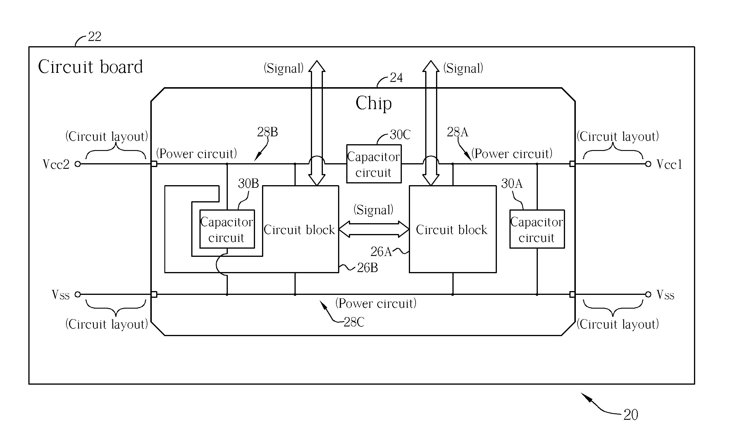
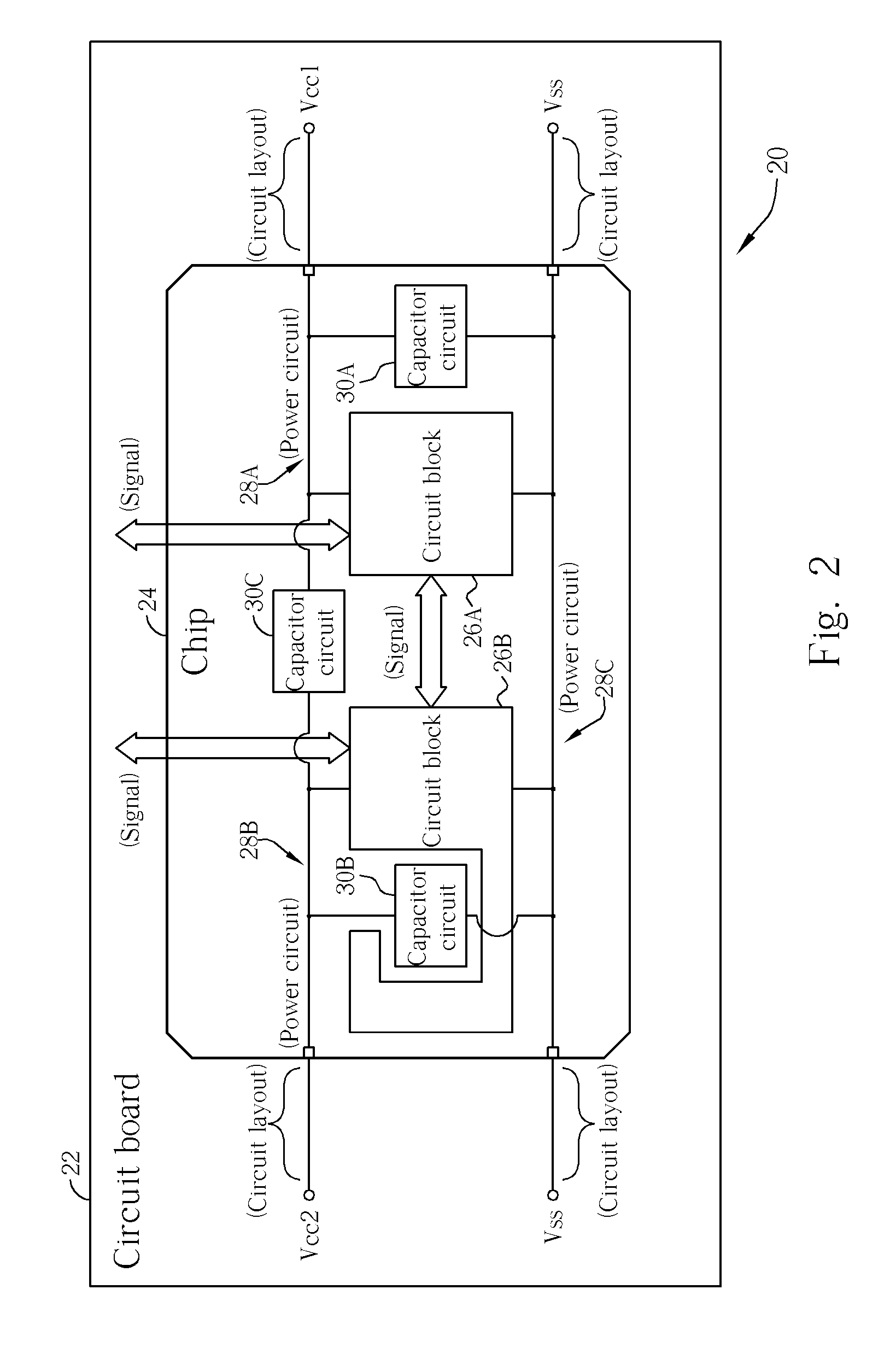
[0013] In order to transfer the power provided by the biases, the chip comprises a layout of power circuits. The claimed invention sets embedded electromagnetic compatibility capacitors between the power circuits of the chip. Therefore, the embedded electromagnetic compatibility capacitors can directly compensate and slow down the sudden electronic change inside the chip, and further reduce the electronic interference and the electromagnetic interference. Because the claimed invention disposes the electromagnetic compatibility capacitors inside the chip, the above-mentioned equivalent resistor and conductor combination can be enormously reduced. Therefore, the high-frequency characteristic and response of the embedded electromagnetic compatibility capacitors is not influenced such that it can reduce the electronic and electromagnetic interference efficiently. On the other hand, the claimed invention can avoid higher production time and costs that are associated with the external capacitor. The result is an increase in the reliability of the electronic system.
[0015] Furthermore, the claimed invention can utilize MOSFETs having different areas to implement capacitors having different capacitance values. The gate of each MOSFET becomes one end of the capacitor, and the source and the drain of each MOSFET becomes another end of the capacitor. Given the present chip manufacturing technology, capacitors can be made to have about 10-1000 PF such that the capacitors can appropriately reduce the electronic and electromagnetic interferences.

Problems solved by technology

Moreover, when the chip has to process and transfer the frequently-changed electronic signal, a high frequency electronic interference and electromagnetic interference often will occur as a result.
These interferences not only wield influence over the normal operation of the chip, but also because of the noise, radiated outside of the chip, other electronic system or even the user themselves are influenced.
Because the chip comprises many circuit units, and each circuit unit obtain the power from each bias at the same time, the bias has a very large power supplying loading.
Therefore, the power supplying loading of the biases changes more violently and frequently.
This causes a sudden electronic change (e.g., a power bounce or a ground bounce) causing unstable biasing voltages and currents such that the electronic interference occurs.
The electronic interference not only influences the normal operation of each circuit unit to form the noise of the electronic signals, but also is coupled to the outside signal wire.
As a result, the electronic interference is transferred to other chips.
In addition, the electronic interference may become a high frequency electromagnetic radiation such that an electromagnetic interference is formed.
Nevertheless, the prior art has its disadvantages.
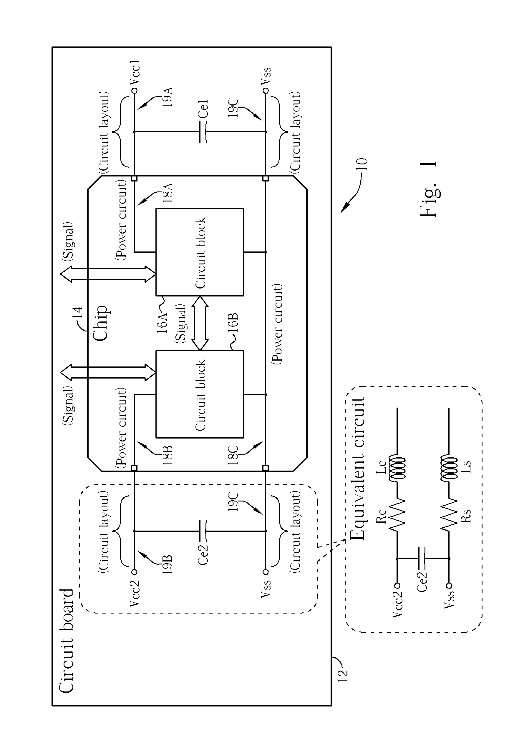
Unfortunately, the equivalent resistor and inductor of the power circuits will combine with the electromagnetic compatibility capacitor.
As a result, the high-frequency response is slowed down such that the whole electromagnetic protection mechanism cannot compensate for the sudden electronic change in an efficient manor.
This increases the production cost and production time of the electronic system.

Method used


Image

  • Chip with embedded electromagnetic compatibility capacitors and related method
  • Chip with embedded electromagnetic compatibility capacitors and related method
  • Chip with embedded electromagnetic compatibility capacitors and related method

Examples


Embodiment Construction

[0020] Please refer to FIG. 1, which is a diagram of the implementation of a external electromagnetic compatibility capacitors in an electronic system 10. As shown in FIG. 1, the electronic system 10 can comprise one or more chips. In addition, each chip of the electronic system can be installed on a circuit board 12 such that each chip can exchange signals and data through the circuit layout of the circuit board, and is electrically connected to each DC bias. For a simplified illustration, only a single chip 14 is shown.

[0021] As mentioned previously, each circuit of the chip has to be appropriately biased to function. In the case shown, in FIG. 1, the chip 14 comprises two circuit blocks 16A and 16B, which are respectively biased by different DC biases. As shown in FIG. 1, the circuit block 16A is biased by the DC biases Vcc1 and Vss (this can be regarded as a ground voltage), and the circuit block 16B is biased by the DC biases Vcc2 and Vss. The two circuit blocks 16A and 16B ca...


PUM


Abstract

Chips with embedded capacitors for electromagnetic compatibility and related method are disclosed. In a chip, sudden electronic changes occur between power circuits for transmitting power of direct current biasing, and lead to electromagnetic interference of high frequency. In the present invention, capacitors for electromagnetic compatibility are directly embedded in the chip, that is, directly embedding build-in capacitors between power circuits of the chip. In this way, sudden electronic changes between power circuits can be effectively absorbed by the embedded capacitors, and electromagnetic interference is then reduced to provide better electromagnetic compatibility and protection.

Description

BACKGROUND OF INVENTION [0001] 1. Field of the Invention [0002] The invention relates to a chip with embedded electromagnetic compatibility capacitors and related method thereof, and more particularly, to a chip with embedded electromagnetic compatibility capacitors placed between biasing power circuits and related method thereof. [0003] 2. Description of the Prior Art [0004] As the manufacturing technique in the processing of the semiconductor has progressed, each electronic system (for example, the computer system) has become one of the most important basic hardware in today's information society. Generally speaking, in the electronic system, one or more chips are built-in. The whole function of the electronic system is implemented by integrating all of the functions of each chip. In order to raise the efficiency of the electronic system, the chip works in a high frequency such that the chip can process more information, manage more data, and transfer more data or signals in a cer...

Claims


Application Information

Patent Timeline
IPC IPC(8): H04B3/00
CPCH01L23/552H01L23/642H01L2924/3011H01L2924/0002H01L2924/00
Inventor KUO, HUNG-YI
Owner VIA TECH INC
Learn More