Optical transmission apparatus, continuity testing method therein, and optical transmission system

a transmission apparatus and continuity testing technology, applied in the field of optical transmission apparatuses, continuity testing methods therein, optical transmission systems, can solve the problems of increasing the splice loss or the quantity of reflectance, the number of operations will be considerable, and the load of operations may be enormous, so as to achieve the effect of shortening the time and reducing the cos

Inactive Publication Date: 2006-11-30
FUJITSU LTD
View PDF8 Cites 21 Cited by
  • Summary
  • Abstract
  • Description
  • Claims
  • Application Information

AI Technical Summary

Benefits of technology

[0021] In the light of the above problems, an object of the present invention is to provide a continuity test on optical propagation paths through optical components disposed for communications over all channels that the apparatus can accommodate including a channel that is not used at the time of a start of the operation, which can be made easier than the known techniques.
[0022] Another object of the present invention is to provide a continuity test on optical propagation paths of all channels that the apparatus can accommodate, which can be made within a shorter time than the known techniques.
[0023] A further object of the present invention is to provide a continuity test on optical propagation paths of all channels that the apparatus can accommodate, which can be made at a lower cost than the known techniques.
[0036] In the above optical transmission system, preferably, the preamplifier is comprised of a fiber amplifier which can amplify an input beam by means of an optical fiber pumped by a pump beam, the first control unit of the first optical transmission apparatus comprises a transmission stop requesting unit for requesting the second optical transmission apparatus connected through the input transmission line to stop transmission of the wavelength-multiplexed signal beam through the input transmission line when an amplified spontaneous emission generation controlling unit generates the amplified spontaneous emission, a response receiving unit for receiving a response that transmission of the wavelength-multiplexed signal beam from the second optical transmission apparatus has been stopped according to a transmission stop request from the transmission stop requesting unit, and a pump beam supply controlling unit for controlling supply of the pump beam to the optical fiber forming the fiber amplifier to generate the amplified spontaneous emission when the response receiving unit receives the response, the second optical transmission apparatus comprises a stop request receiving unit for receiving the request from the transmission stop requesting unit, a stopping process unit for stopping transmission of the wavelength-multiplexed signal beam to the first optical transmission apparatus according to the request received by the stop request receiving unit, and a response transmitting unit for transmitting to the first optical transmission apparatus an effect that stopping of the transmission of the wavelength-multiplexed signal beam is completed as a response when said stopping process unit stops the transmission of the wavelength-multiplexed signal beam.
[0037] As above, the present invention has an advantage that since amplified spontaneous emission is used as a probe beam for the continuity test under the control of the preamplifier controlling unit and the first control unit, the continuity test on optical propagation paths of all channels that the apparatus can accommodate including a channel not used at the time of a start of the operation can be made easier than the known techniques.
[0038] The present invention has another advantage that since it becomes unnecessary to prepare a wavelength tunable laser or the like for the continuity test, the continuity test on optical propagation paths of all channels that the apparatus can accommodate can be made within a shorter time and at a lower cost than the known techniques.

Problems solved by technology

Adoption of optical connectors for the connections may increase the splice loss or the quantity of reflectance because of contaminants adhering on the spliced surface of the connector.
When the splice loss or the quantity of reflectance is considerable, it may cause disconnection due to degradation of the transmission quantity such as the bit error rate.
However, if the continuity test is performed on each of all the points at which the connectors are mounted, the number of times of the operation will be considerable because the number of the points is considerable.
With respect to an optical apparatus other than the OADM node, the load of the operation may be enormous at the time of the continuity test on the apparatus that has a function of demultiplexing wavelengths of a wavelength-multiplexed optical signal.
However, in a system using an optical amplifier for collectively amplifying wavelength-multiplexed signals, the maintenance work such as cleaning or the like of a connector spliced surface requires all the channels to be once stopped, in many cases.
There have been problems that it is necessary to separately prepare an element such as a wavelength tunable laser that can output a light beam having each channel in order to test the continuity, that the cost increases when the continuity testing function is given to the node apparatus, and that a longer time is required until the commercial operation is started because the load on the operator who controls the wavelength tunable laser increases.

Method used


Image

  • Optical transmission apparatus, continuity testing method therein, and optical transmission system
  • Optical transmission apparatus, continuity testing method therein, and optical transmission system
  • Optical transmission apparatus, continuity testing method therein, and optical transmission system

Examples


first embodiment

[A] Description of First Embodiment

[A1] As to Optical Transmission System According to First Embodiment of the Invention

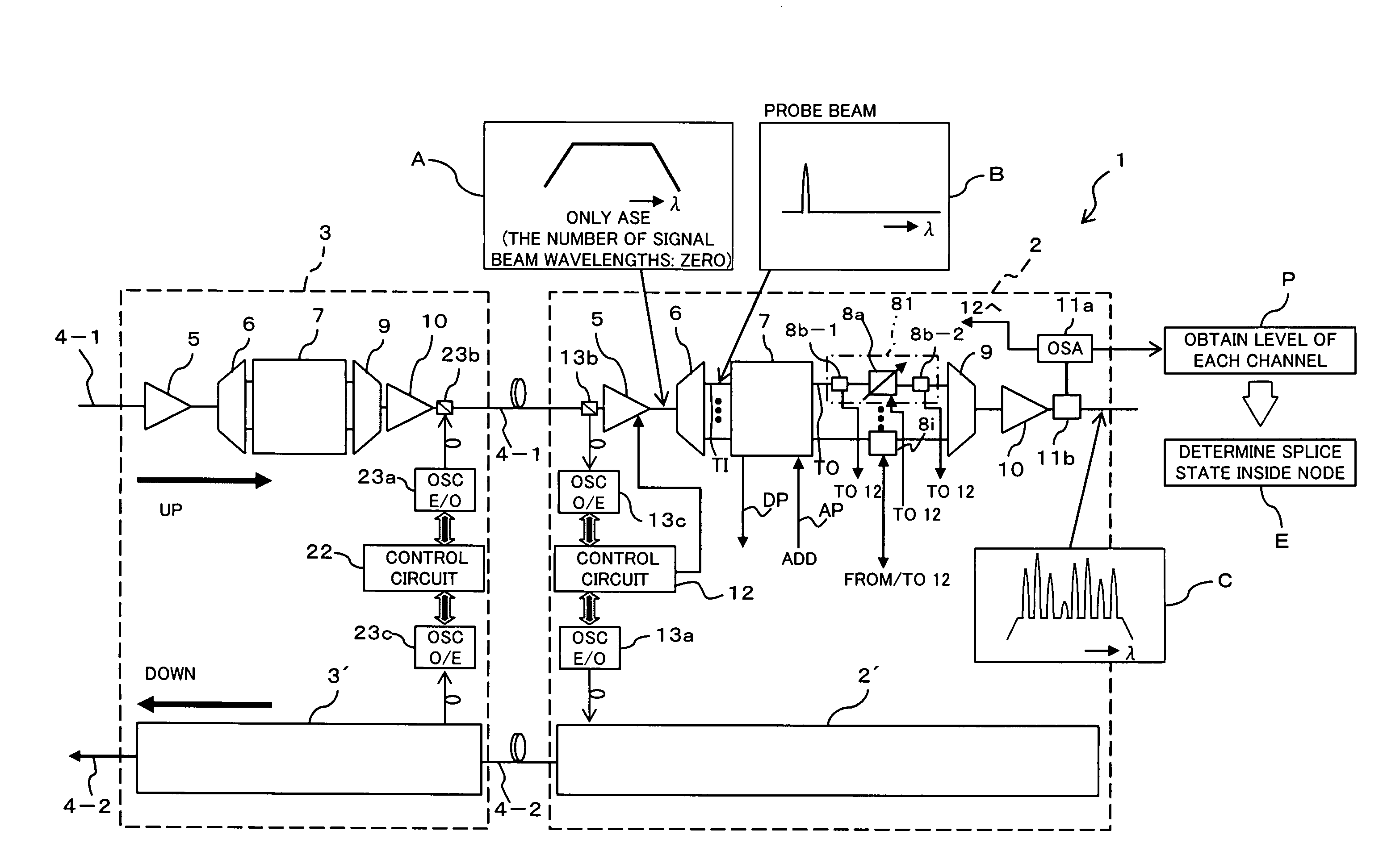
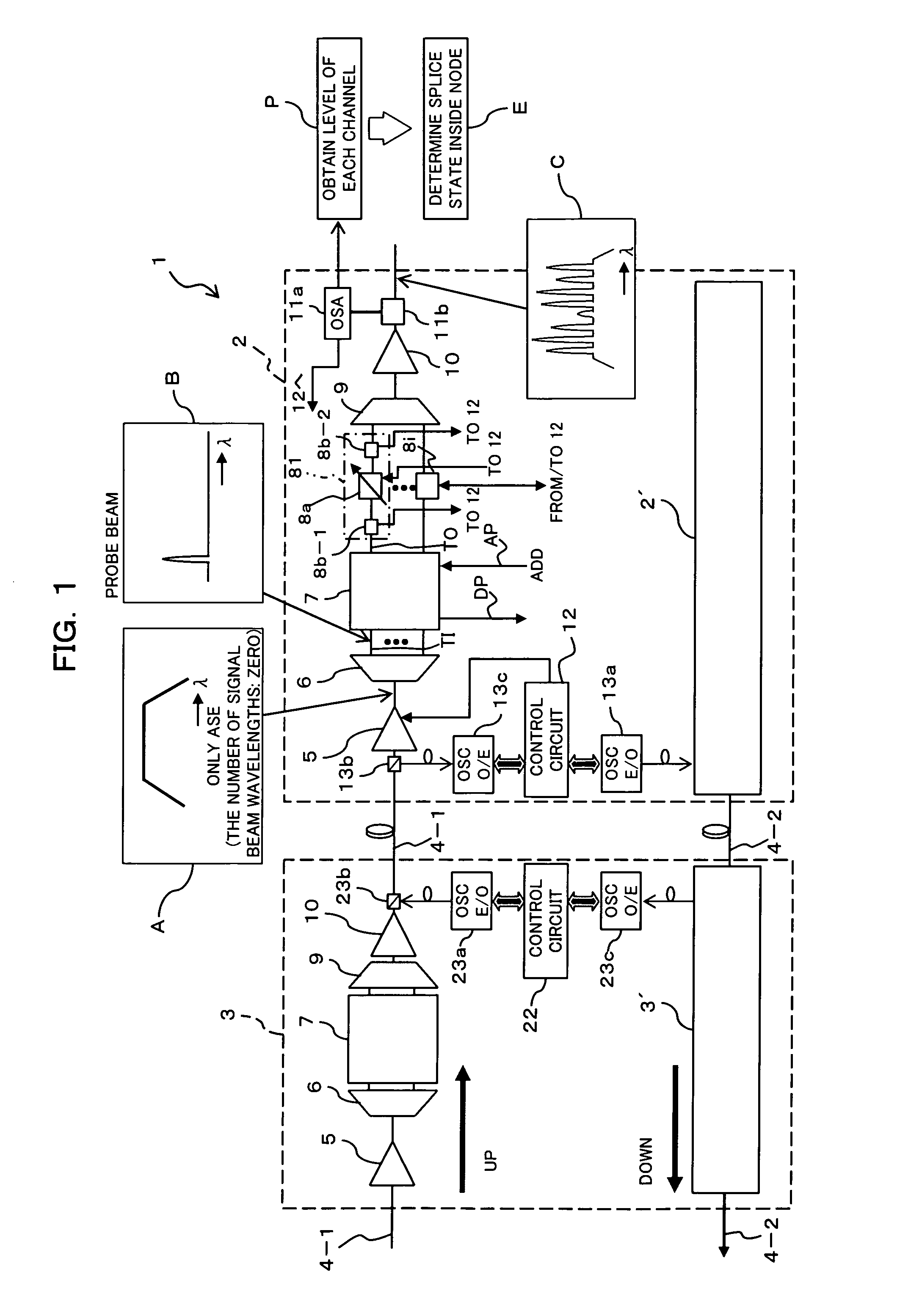
[0052]FIG. 1 is a diagram showing an optical transmission system 1 according to a first embodiment of this invention. The optical transmission system 1 shown in FIG. 1 is a part of a ring network configuring a WDM network in a metro network, in which two OADM apparatuses (first and second OADM apparatuses 2 and 3) for dropping or adding a wavelength-multiplexed channel are connected in cascade to each other through transmission lines 4-1 and 4-2.

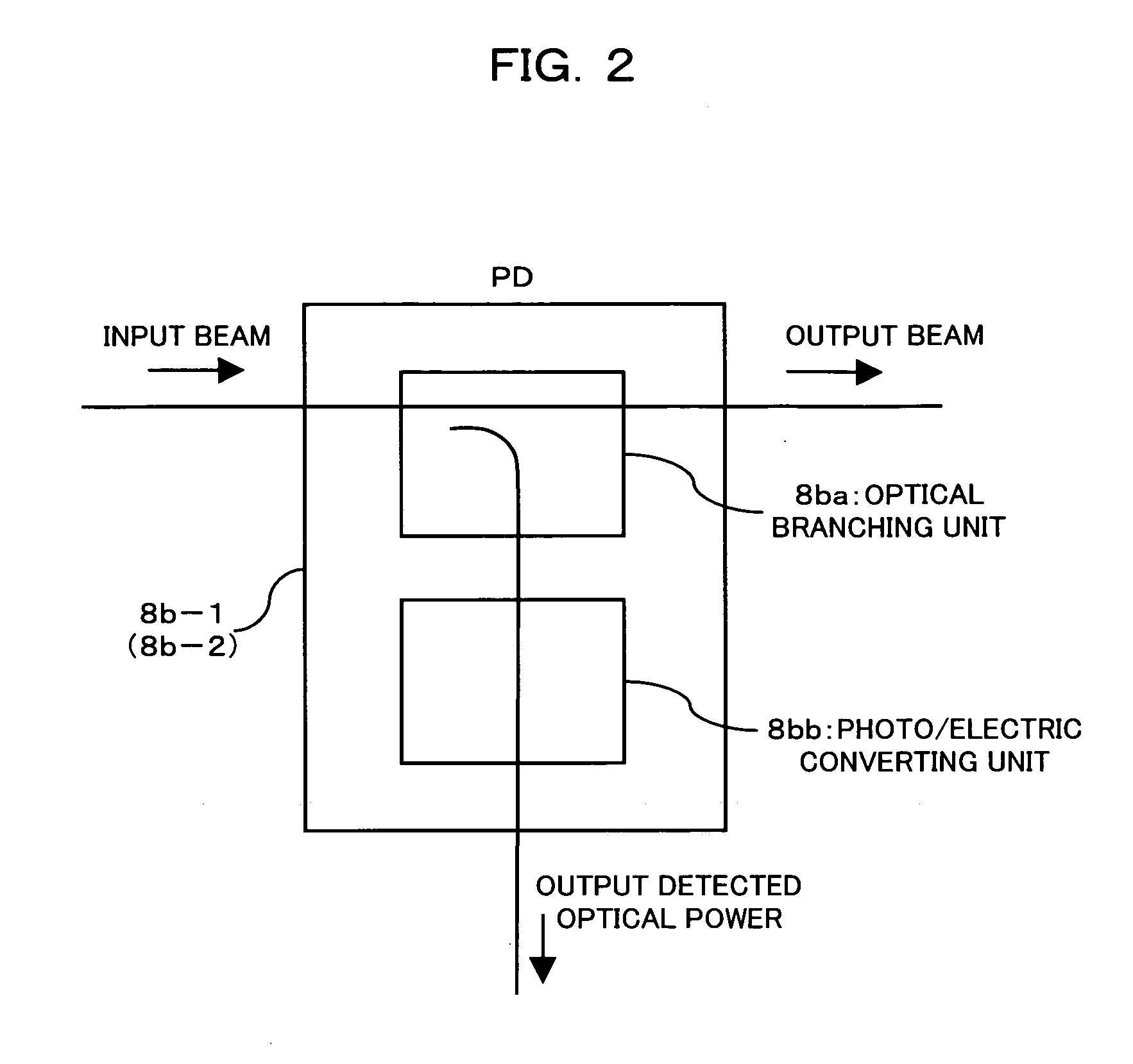
[0053] Each of the OADM apparatuses 2 and 3 has an optical add / drop function basically similar to that shown in FIG. 11 described above. However, the first OADM apparatus 2 has a characteristic structure for continuity confirmation of an optical propagation path (that is, a path configured with optical coupling of optical components disposed for each channel in the first OADM apparatus 2) of each channel of a wavelength-...

second embodiment

[B] Description of Second Embodiment

[B1] As to Optical Transmission System According to Second Embodiment of the Invention

[0124]FIG. 6 is a diagram showing an optical transmission system 1A according to a second embodiment of this invention. As compared with the optical system 1 described above according to the first embodiment, the optical transmission system la shown in FIG. 6 is similar to that according to the first embodiment in that two OADM apparatuses (a first and a second OADM apparatuses 2A and 3A) are connected in cascade to each other through the up-link or down-link transmission line 4-1 or 4-2, but different from that according to the first embodiment in that the structure for the continuity test to be made in the first OADM apparatus 2A, and the mode of the same are different from those according to the first embodiment. Incidentally, an illustration of the structure for the add / drop process for a beam propagating through the down-link transmission line 4-2 is omitt...


PUM


Abstract

An optical transmission apparatus comprises a preamplifier controlling unit for controlling a preamplifier so that amplified spontaneous emission including all wavelength bands of a wavelength-multiplexed signal beam is outputted toward a wavelength demultiplexing unit, with the wavelength-multiplexed signal beam not inputted, power monitors for monitoring optical powers of the amplified spontaneous emission fed from the preamplifier and wavelength-demultiplexed by the wavelength demultiplexing unit, and a determining unit for determining the continuity state of an optical propagation path of each wavelength component on the basis of a result of monitoring by the power monitors. The optical transmission apparatus allows the continuity test on optical propagation paths of channels including a channel not used at the time of a start of the operation to be made easier than the known techniques.

Description

BACKGROUND OF THE INVENTION [0001] 1) Field of the Invention [0002] The present invention relates to an optical transmission apparatus, a continuity testing method therein, and an optical transmission system suitable for use in an optical communication system having the wavelength division multiplexing (WDM) function. [0003] 2) Description of the Related Art [0004] In the field of the optical communication networks having the WDM function, the DWDM (Dense WDM) technique is introduced into not only known long-distance (long-haul) networks but also local (metro) networks because of a recent rapid increase in communication traffic. In the WDM network, an optical add drop multiplexer (OADM) for adding a channel to be wavelength-multiplexed or dropping a channel is appropriately arranged as a node. [0005] Particularly, many WDM networks in the metro networks adapt a network configuration in which a number of OADM nodes are arranged in a ring. With expansion of the network scale in the fu...

Claims


Application Information

Patent Timeline
Patent Type & Authority Applications(United States)
IPC IPC(8): H04B10/08H04B10/073H04B10/077H04B10/27H04B10/275H04B10/297H04J14/00H04J14/02
CPCH04B10/077H04B2210/258H04B10/296H04B10/07955
Inventor FUJITA, TAKEHIRO
Owner FUJITSU LTD
Why Eureka
Try Eureka