Data management method and data management system

a data management system and data management technology, applied in the field of facility data management, can solve the problems of inability to figure out the location of underground facilities, enormous cost and time, and waste of resources, and achieve the effect of convenient management system, quick and sure data on site, and easy access to facilities

Inactive Publication Date: 2006-12-07
SEMICON ENERGY LAB CO LTD
View PDF9 Cites 6 Cited by
  • Summary
  • Abstract
  • Description
  • Claims
  • Application Information

AI Technical Summary

Benefits of technology

[0016] In view of the aforementioned problems, the present invention solves problems such as a power source problem or such that a sign is exposed to the ground level, and provides a managing system which can obtain data on facilities simplify, promptly and surely. In addition, the present invention provides a managing system having an improved security function.
[0017] The present invention performs data management of a managed object by attaching a wireless chip to a facility itself which is buried in the underground or the like. In a case where data management related to a certain facility is performed, the wireless chip is attached to the facility itself, so that a stake or the like that is required for management of the facility is not required to be provided on the ground and a land can be effectively used.
[0018] In addition, by a facility data management system of the present invention, by incorporating a CUP (Central Processing Unit) in a wireless chip, only a terminal having an encryption function which has obtained permission of communication can communicate, and access by unspecified number of devices, leakage of position data or the like, an erasure of stored data, rewriting or the like can be prevented.
[0030] By using the facility data management system of the present invention, it is not required to provide a stake on the ground so that the land can be used effectively.
[0031] A wireless chip using a CPU is used for the facility data management system of the present invention, so that only a terminal having an encryption function which has obtained permission of communication can communicate, and access by unspecified number of devices, leakage of position data or the like, an erasure of stored data, rewriting or the like can be prevented.
[0033] By using such a facility data management system of present invention, only data required from among data which is associated with many underground facilities or ground facilities can be received by a reader / writer from a data processor when necessary. As a result, an enormous amount of data on facilities can be obtained easily, promptly and surely on site, and a more convenient managing system can be realized.

Problems solved by technology

In particular, as for a public facility under the ground, there are record documents at the time of establishment construction of each facility, documentary photographs, drawings or the like; however, there are no general associated documents so much, and it is impossible to figure out where an underground facility is located without digging up a land surface near the spot in maintenance or additional construction.
Further, in a case where an underground facility is managed in such a work, considering the enormous number of documents, the number of people who are involved with the management of electric power, communication, gas, water, sewage or the like, and expended hours, enormous cost and time are needed.
In storing data in paper or the like conventionally, there have been problems in deterioration of the paper which is a storage medium, problems in a filing method, and problems in difficulty of data sharing; therefore, there is a problem in that enormous data can be used for only some specific people.
By a conventional method, a boundary stake showing a land border location, or a display stake showing kinds and locations of each facility such as underground facility is provided innumerably, so that its management or an installation site becomes a problem.
For example, in construction of a driveway or a sidewalk, or construction of a building, a public institution or the like, there are problems such as limitation of these construction forms, limitation of a construction place, a long construction period, and increase of expenses due to exposure of the sign to the ground level.
In addition, by a method shown in Patent Document 2, when a wireless terminal portion and a memory chip portion transmit / receive data, there is a problem in a memory chip operation without being described from where an operation power source of the memory chip portion is obtained.
In addition, a method in which a main body which is in a state of being exposed to a top part of the ground level is buried in the ground is used in Patent Document 3; however, there are problems such as limitation of a construction form, limitation of a construction place, a long construction period, and increase of expenses due to exposure of a sign to the ground level.
Furthermore, since position data is obtained by the GPS, special equipment is necessary, which leads to the increase of the construction cost.

Method used


Image

  • Data management method and data management system
  • Data management method and data management system
  • Data management method and data management system

Examples


embodiment mode 1

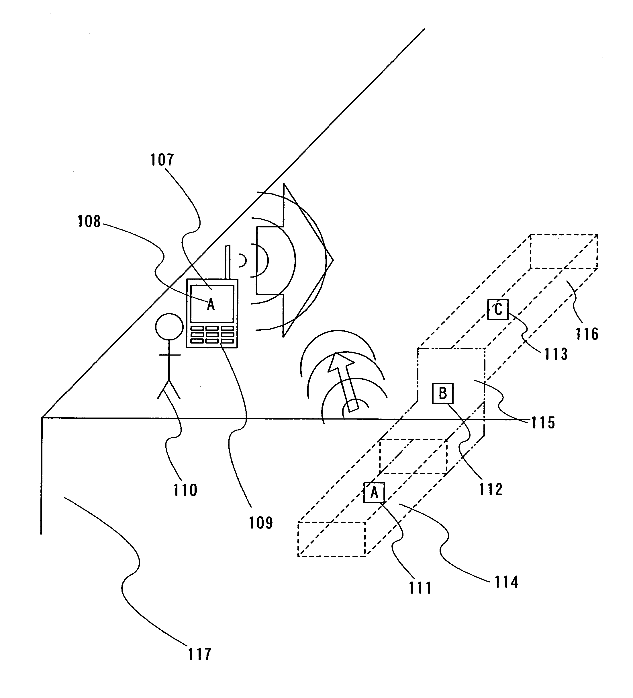
[0050] In this embodiment mode, a facility such as an underground installation is used as an example of a managed object and a data management system structure of the facility is described.

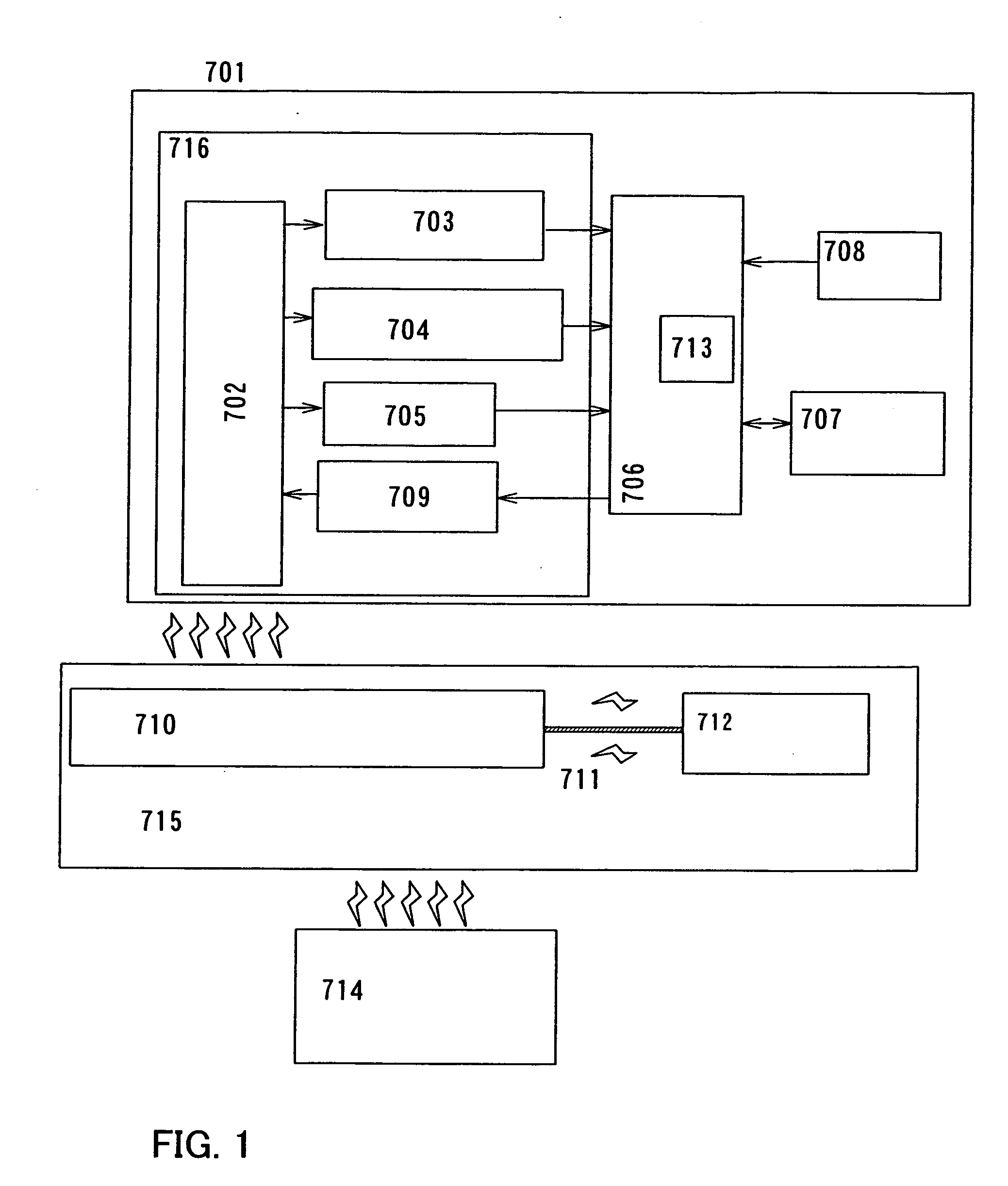
[0051] A wireless chip 701 of the present invention has a resonant circuit 702 having an antenna and a resonant capacitor, a power supply circuit 703, a clock generator circuit 704, a demodulation circuit 705, a control circuit 706, a memory circuit 707 provided with a memory element such as a write-once memory, a modulation circuit 709, an A / D converter circuit 708, a CPU 713, and an RF circuit 716 as shown in FIG. 1.

[0052] The RF circuit 716 has the resonant circuit 702, and the resonant circuit 702 is connected to the power supply circuit 703, the clock generator circuit 704, the demodulation circuit 705, and the modulation circuit 709, and performs exchanges of signals and power. Signals from the power supply circuit 703, the clock generator circuit 704, and the demodulation circuit 705 are ...

embodiment mode 2

[0090] In this embodiment mode, description is made of the memory circuit 707 that the wireless chip 701 has, and an operation method thereof.

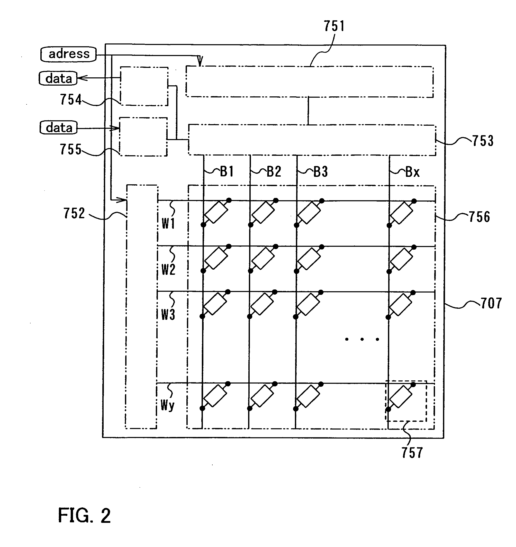
[0091] As shown in FIG. 2, the memory circuit 707 includes a memory cell array 756 in which memory elements are formed and a driver circuit. The driver circuit includes a column decoder 751, a row decoder 752, a reading circuit 754, a writing circuit 755, and a selector 753.

[0092] The memory cell array 756 includes a bit line Bm (m=1 to x), a word line Wn (n=1 to y), and a memory cell 757 each at an intersection between the bit line and the word line. Note that the memory cell 757 may be either an active type in which a transistor is connected or a passive type which is constituted only by a passive element. In addition, the bit line Bm is controlled by the selector 753 and the word line Wn is controlled by the row decoder 752.

[0093] The column decoder 751 receives an address signal for specifying an arbitrary bit line and supplies a signal...

embodiment mode 3

[0120] In this embodiment mode, a cross sectional diagram of the memory circuit 707 is described.

[0121]FIG. 5A is a cross sectional diagram of a memory element in which a memory cell portion 501 and a driver circuit portion 502 are integrally formed over an insulating substrate 510. As the insulating substrate 510, a glass substrate, a quartz substrate, a substrate formed of silicon, a metal substrate, a plastic substrate or the like can be used. When the plastic substrate is used, a thin, lightweight wireless chip can be provided. Further, polishing is performed for the glass substrate or the like, so that a further thinner and lighter-weight wireless chip can be realized.

[0122] A base film 511 is formed over the insulating substrate 510. In the driver circuit portion 502, thin film transistors 520 and 521 are provided over the substrate 510 with the base film 511 interposed therebetween, and in the memory cell portion 501, a thin film transistor 621 is provided over the substrat...


PUM


Abstract

In managing an underground facility, considering the enormous number of documents, the number of people who are involved with the management of electric power, communication, gas, water, sewage or the like, and expended hours, enormous cost and time have been needed so far. A wireless chip is attached to each buried object itself in substitution for a boundary stake or a display stake of an underground facility or a ground facility. Then, data such as embedded date, position data, or an owner is written into a memory portion of the wireless chip. In addition, by incorporating a CUP in the wireless chip, only a terminal having an encryption function which has obtained permission of communication can communicate, and access by unspecified number of devices, leakage of position data or the like, an erasure of stored data, rewriting, and the like can be prevented. Such a system can surely perform management of facility data.

Description

BACKGROUND OF THE INVENTION [0001] 1. Field of the Invention [0002] The present invention relates to a method for managing facility data such as underground and a system for the method. [0003] 2. Description of the Related Art [0004] Boundary stakes showing a land border location and display stakes showing a location of each facility such as electric power cables, communication cables, gas pipes, water pipes, sewage pipes, and another underground facility which are buried in public underground facilities such as roads and sites have been provided innumerably on Japanese land so far. [0005] In particular, as for a public facility under the ground, there are record documents at the time of establishment construction of each facility, documentary photographs, drawings or the like; however, there are no general associated documents so much, and it is impossible to figure out where an underground facility is located without digging up a land surface near the spot in maintenance or additi...

Claims


Application Information

Patent Timeline
Patent Type & Authority Applications(United States)
IPC IPC(8): G06Q30/00G06K19/06
CPCG06Q10/06H01L27/12G11C17/18G11C17/14
Inventor OHSHIMA, KAZUAKI
Owner SEMICON ENERGY LAB CO LTD
Why Eureka
Try Eureka