OLED device having curved viewing surface

a technology of oled devices and viewing surfaces, which is applied in the direction of thermoelectric devices, sustainable manufacturing/processing, and final product manufacturing, etc., can solve the problems of cracking and moisture permeation of the structure, the rigid structure of the typical structure is not easy to adapt to a curved configuration, and the individual mounting of light emitting diodes is expensive and only suitable for low-resolution displays

Active Publication Date: 2006-12-07
GLOBAL OLED TECH
View PDF11 Cites 264 Cited by
  • Summary
  • Abstract
  • Description
  • Claims
  • Application Information

AI Technical Summary

Problems solved by technology

However, because these devices utilize a collection of point light sources, they require additional optical devices such as mirrors and lenses for suitable area illumination.
When applied to information display, individually mounted light emitting diodes are expensive and only suitable for low-resolution displays.
Such structures are typically very rigid and difficult to employ in a curved configuration.
Typically, problems such as cracking and moisture permeation are encountered in such flexible devices.
However, the main problems associated with the use of glass as a substrate in electric or semiconductor devices are its high specific weight, brittleness and limited flexibility.
The latter problems require the coating of a functional layer on glass to be typically carried out in a batch process (sheet by sheet).
Plastic is typically very flexible, shock resistant, and light weight, but is also porous and many light-emitting materials, for example OLEDs are sensitive to environmental contamination that may permeate a plastic substrate.
Some progress has been made on producing plastic foils with barrier layers to limit permeability; however the lifetime of electric devices in which such plastic foils are used is still limited and needs to be improved.
In addition, an inorganic conducting layer such as indium-tin oxide (ITO) is brittle and as a result, the electroconductivity of an ITO layer is susceptible to deterioration by simply bending a flexible plastic substrate.
All these effects limit the lifetime of such flexible plastic substrate based devices considerably.
Other problems associated with plastic substrates include inorganic electroconductive layers such as ITO may require an annealing step at an elevated temperature which is not compatible with most plastics.
Nonetheless, continuous flexing of such structures can lead to failure and may not provide the process compatibility necessary for OLED display processing.
However, such a design still requires that an entire display screen itself be flexible, and therefore suffers from the same environmental exposure and lifetime problems found in the OLED flexible display art.
Such flexible display design still fails to teach encapsulation of a curved display in a manner that solves the environmental exposure and lifetime problems found in the OLED flexible display art.
Most display manufacturing equipment, however, is designed for planar surfaces so that the deposition of materials on a curved surface is difficult and the manufacturing infrastructure for supporting such deposition is not available.

Method used


Image

  • OLED device having curved viewing surface
  • OLED device having curved viewing surface
  • OLED device having curved viewing surface

Examples


Embodiment Construction

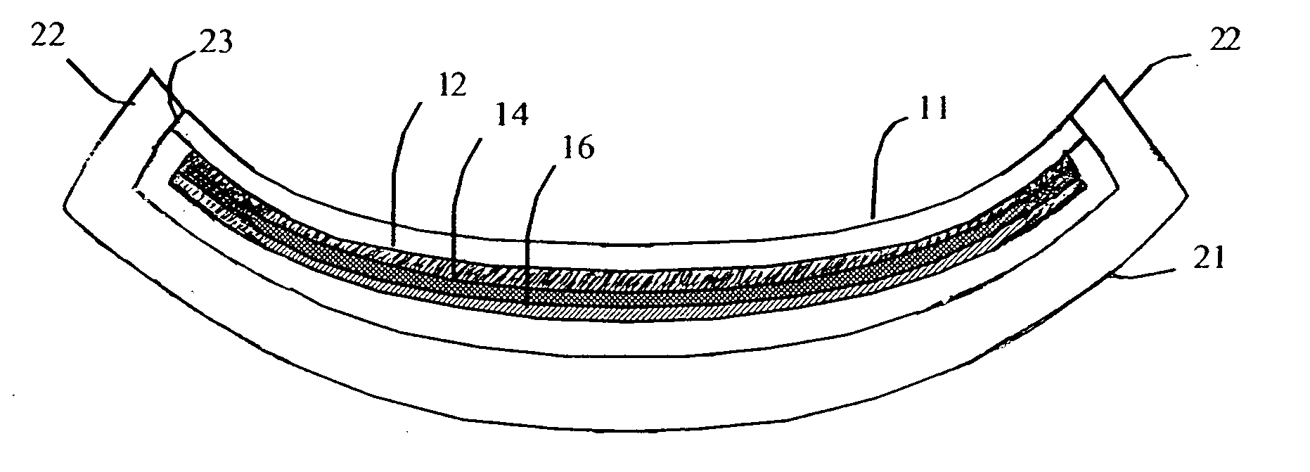
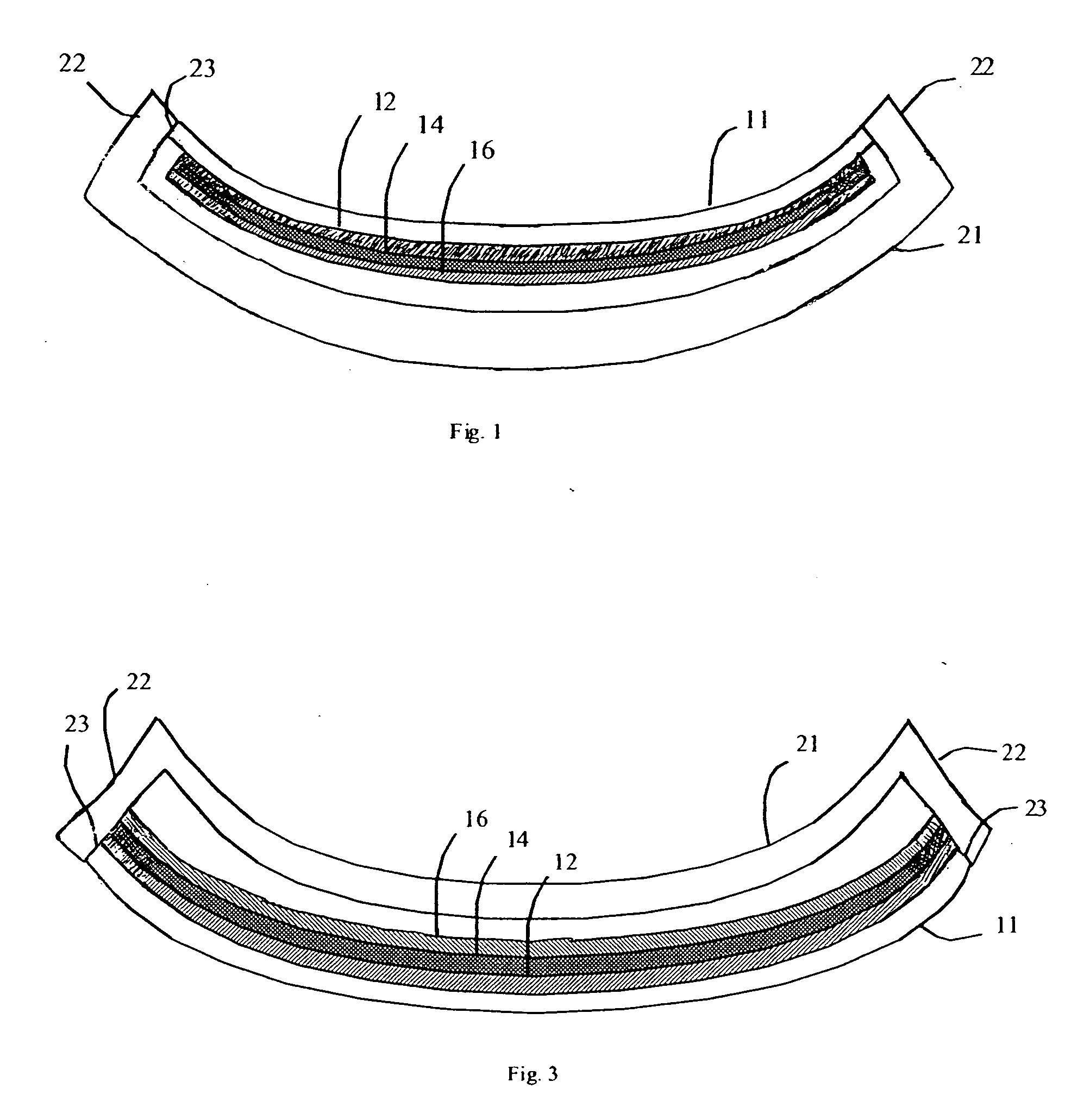
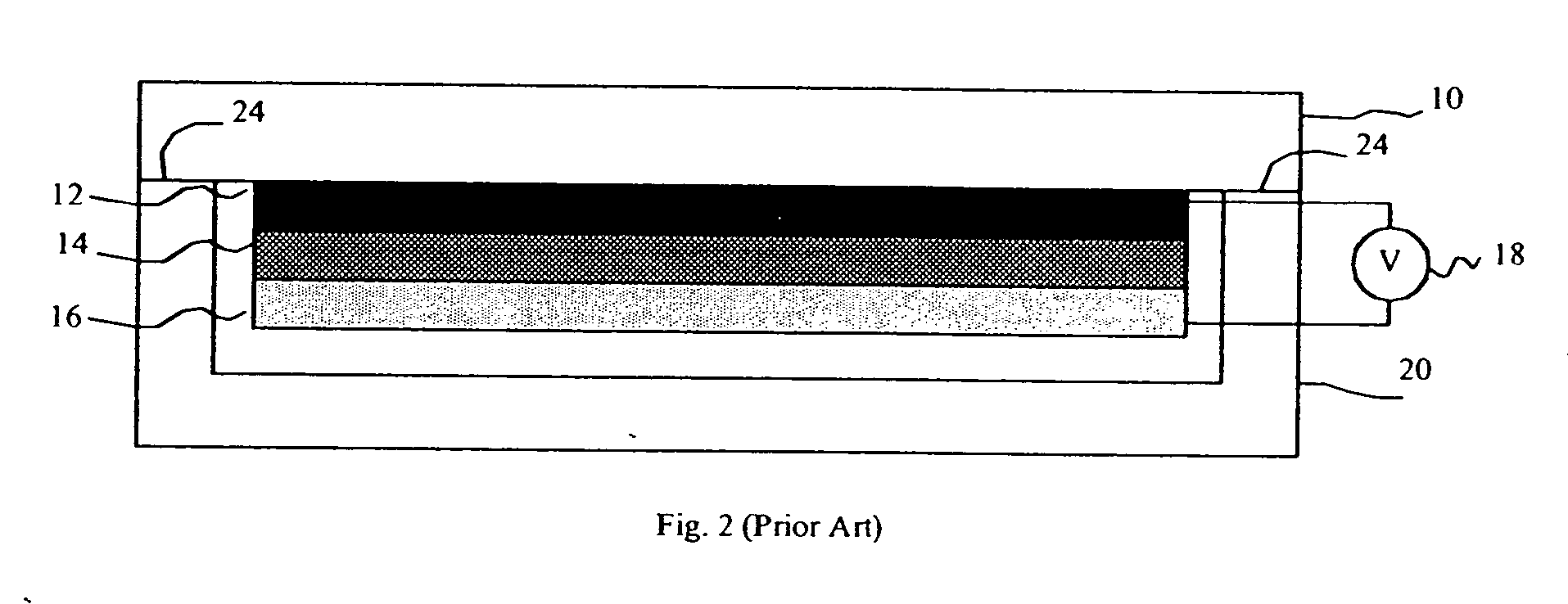
[0033] Referring to FIG. 9, a method of manufacturing an OLED device with a curved light-emitting surface comprises the steps of forming 100 a flexible substrate; flattening 105 the flexible substrate to provide the flexible substrate in a flat configuration; forming 110 one or more OLEDs having a first electrode, one or more layers of organic material, at least one of which is light-emitting formed over the first electrode, and a second electrode formed over the one or more layers of organic material, on the flexible substrate while in the flat configuration; forming 115 a rigid, curved, encapsulating cover; conforming 120 the flexible substrate, electrodes, and one or more layers of organic material to the rigid, curved, encapsulating cover; and sealing 125 the conformed flexible substrate, electrodes, and one or more layers of organic material to the rigid, curved, encapsulating cover. The process is then complete.

[0034] The formation of substrates and covers suitable for the pr...


PUM

PropertyMeasurementUnit
thicknessaaaaaaaaaa
thickaaaaaaaaaa
flexibleaaaaaaaaaa

Abstract

A method of manufacturing an OLED device with a curved light-emitting surface comprising: a) forming a flexible substrate and providing the flexible substrate in a flat configuration; b) forming one or more OLEDs having a first electrode, one or more layers of organic material, at least one of which is light emitting formed over the first electrode, and a second electrode formed over the one or more layers of organic material, on the substrate; c) forming a rigid, curved, encapsulating cover; d) conforming the flexible substrate, electrodes, and one or more layers of organic material to the rigid, curved, encapsulating cover; and e) sealing the conformed flexible substrate, electrodes, and one or more layers of organic material to the rigid, curved, encapsulating cover.

Description

FIELD OF THE INVENTION [0001] The present invention relates to OLED devices and, more particularly, to OLED devices having a curved format. BACKGROUND OF THE INVENTION [0002] Light-emissive devices are well known and used for a wide variety of purposes, including area illumination and the representation of information in displays. Traditionally, these light-emissive devices rely on evacuated glass enclosures within which are special gases, phosphors, or filaments that emit light upon the application of a current or when stimulated with an electron. More recently, solid-state light-emissive devices have created robust, long-lived, and practical displays using, for example, light-emitting diodes, liquid crystal, and plasma technologies. [0003] Light emissive devices are useful in a variety of forms. Traditional forms include bulbs rounded in one or two dimensions, for example incandescent and fluorescent light bulbs. Neon lighting is often linear and is used to create lines of light t...

Claims


Application Information

Patent Timeline
Patent Type & Authority Applications(United States)
IPC IPC(8): H01L51/00H01L51/40
CPCH01L51/0096H01L51/0097Y02E10/549H01L51/5237H01L2251/5338H01L51/52Y02P70/50H10K77/10H10K77/111H10K50/80H10K50/841H10K50/8428H10K2102/311
Inventor COK, RONALD S.
Owner GLOBAL OLED TECH
Why Eureka
Try Eureka