
Connectable rod system for driving downhole pumps for oil field installations

a technology of connecting rods and oil field installations, applied in the direction of bolts, drilling pipes, fastening means, etc., can solve the problems of fatigue failure, large gaps and movements, etc., and achieve the effects of being resistant, unique and useful tension and compression pre-stress relationships, and high torque capabilities

Inactive Publication Date: 2006-12-07
CARSTENSEN KENNETH J
View PDF20 Cites 33 Cited by
  • Summary
  • Abstract
  • Description
  • Claims
  • Application Information

AI Technical Summary

Benefits of technology

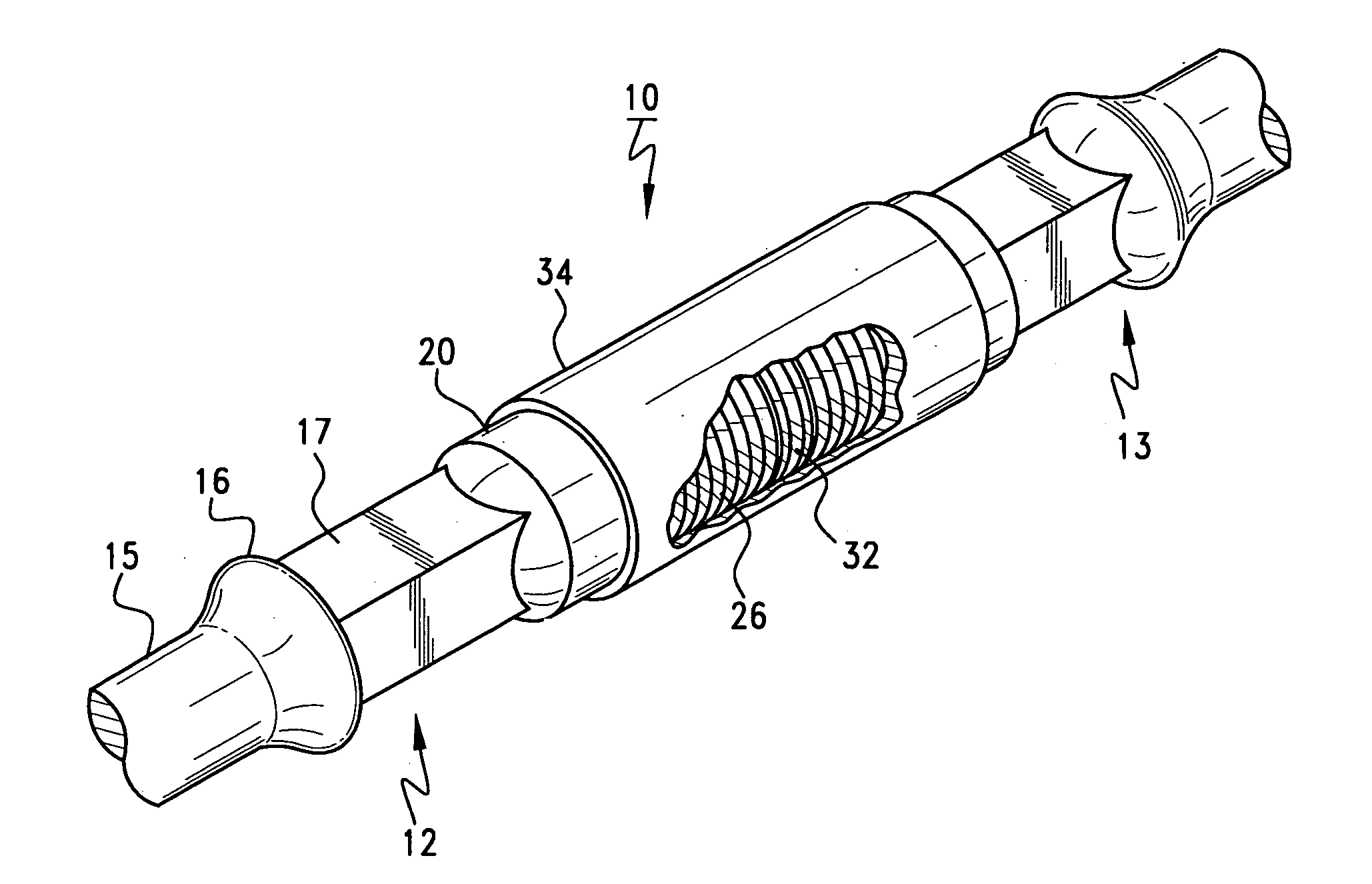
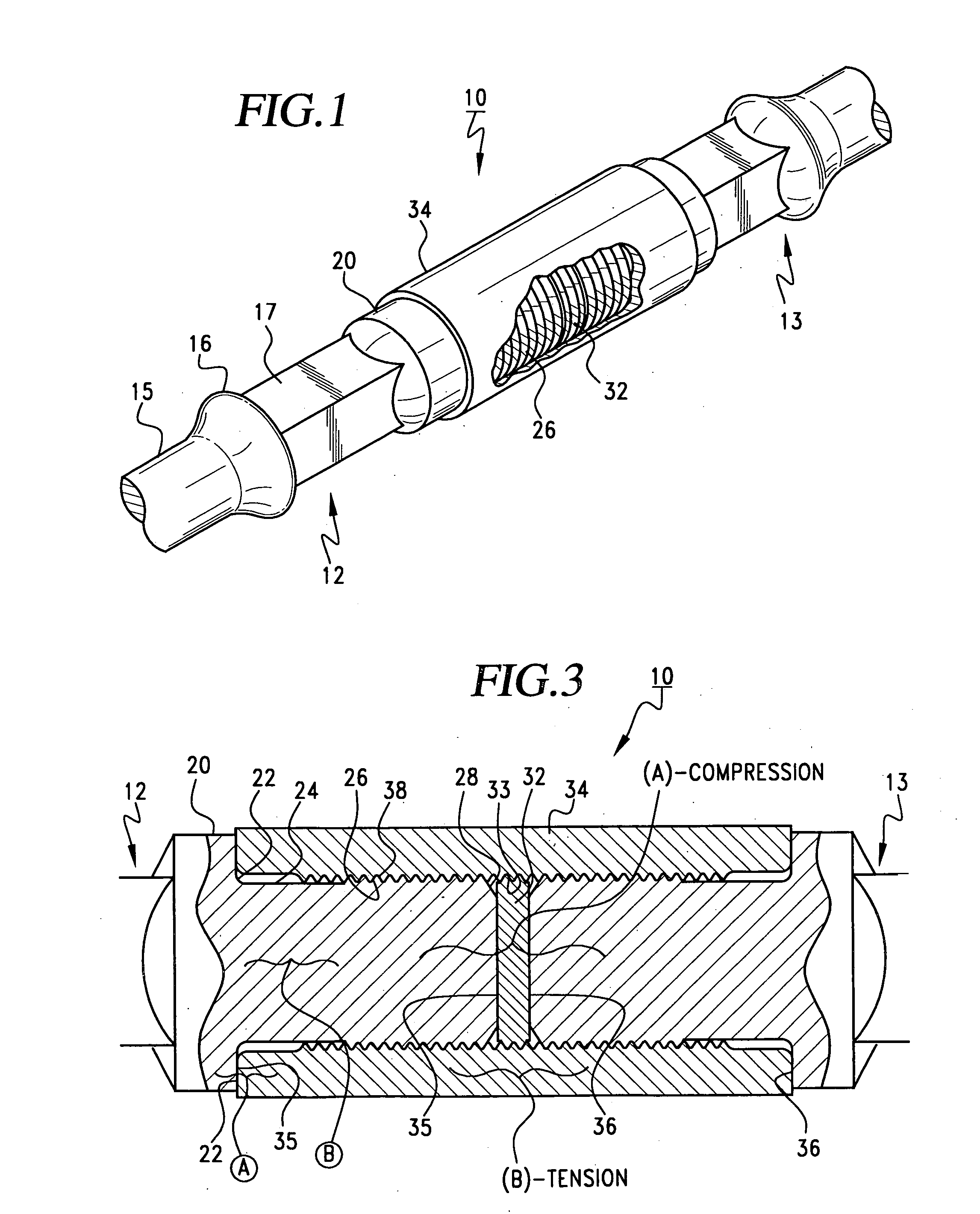
[0011] Systems and devices in accordance with the invention employ a modified API sucker rod end area configuration, in a combination which unifies the pin ends with the coupler so as to yield higher torque capabilities and be resistant to the causes of fatigue failures, while also establishing unique and useful tension and compression pre-stress relationships and enabling a simplified and assured make up sequence.
[0012] Rod connections in accordance with the invention employ controlled force engagement between the end faces of opposing pins so as to compressively pre-stress the threaded pin ends, and also restrain the pin end beyond the pin neck and substantially tension the coextensive lengths of the coupler mid-section. By controlled axial and azimuthal restraints at opposite limits of the pin ends the male and female thread surfaces are locked together, inhibiting the minute physical displacements, even down to the microstructure level in the parts making up the unified combination, which eventually lead to larger gaps and movements, and ultimately fatigue failure. The pin end faces have opposing flat surfaces in areal compressive contact either with interposed torque washers, or each other, materially enhancing the restraints against both axial skewing and azimuthal shifting and doubling the material area in frictional contact that resists back-out. Assembly of the threaded members is aided by use of an anaerobic adhesive compound that thereafter resists back-out and provides an effective seal as well.
[0013] By close control and some prescreening, or by precise machine finishing of certain surfaces on the pin and coupler, the advantages of this new approach are maximized in terms of both the mechanical connection and ease and precision of assembly at the work-over rig. An existing sucker rod inventory can still be employed in utilizing the new approach. Once prepared, threaded engagement of the pin end into a coupler to a given dimension beyond hand tight engagement positions the pin end face at a chosen depth in the coupling. The length tolerances used are closely specified, so that when both pins are set in place and tightened, the pre-stress tension and compression levels are assured. Thus the connection can be first half assembled at a base site with one pin end properly engaged, and a crew at the rig site can quickly and reliably complete the connection with the second pin end merely by controlled circumferential displacement past the hand tight plane.

Problems solved by technology

By controlled axial and azimuthal restraints at opposite limits of the pin ends the male and female thread surfaces are locked together, inhibiting the minute physical displacements, even down to the microstructure level in the parts making up the unified combination, which eventually lead to larger gaps and movements, and ultimately fatigue failure.

Method used


Image

  • Connectable rod system for driving downhole pumps for oil field installations
  • Connectable rod system for driving downhole pumps for oil field installations
  • Connectable rod system for driving downhole pumps for oil field installations

Examples


Embodiment Construction

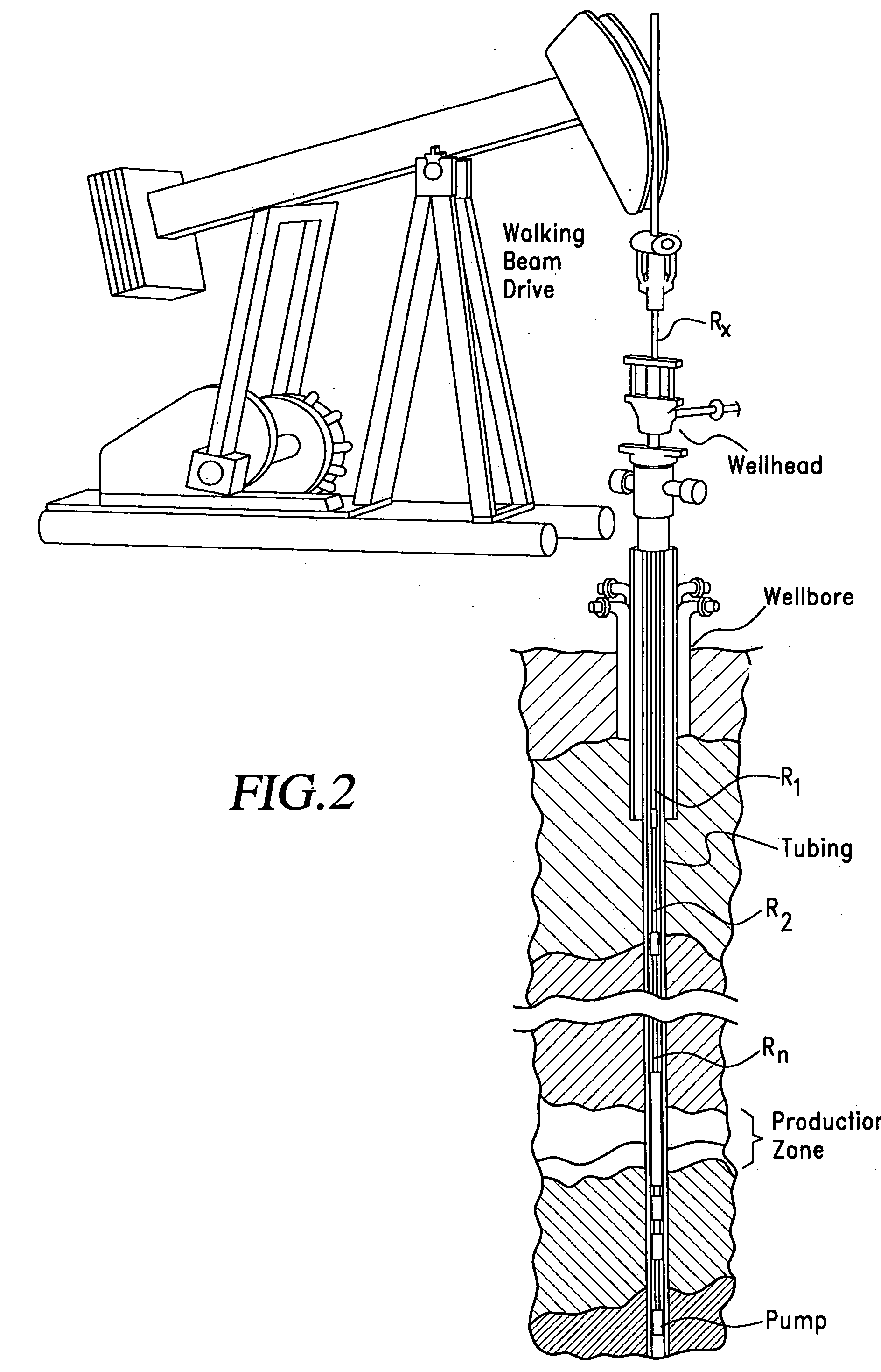
[0036] The drive connection or linkage between production equipment at the surface of an artificial lift installation and the pump at the downhole oil or gas bearing zone comprises a sucker rod string formed of a series of rods of a given length (typically between 25-30 feet long and in a selected size from ½″ to 1 and ⅛″ in diameter). The sucker rod string is within the interior of the production tubing via which oil is lifted to the surface, and the elements of the string must withstand the static and cyclic stresses encountered, the inevitable frictional forces and the cumulative effects of long term cycling. When modern directional drilling techniques are used to form curved well bores, such stresses and forces increase considerably over a purely vertical installation, for both reciprocating and rotary pumps.

[0037] A sucker rod coupling system in accordance with the invention is usable with different downhole pumps, but the principal example is of a conventional reciprocating p...


PUM

PropertyMeasurementUnit
lengthaaaaaaaaaa
circumferential displacementaaaaaaaaaa
sizeaaaaaaaaaa

Abstract

Improved sucker rod joints for down hole petroleum pumping applications are provided within the form factor of standard API sucker rods, such that existing inventory in suitable condition is fully usable in more demanding applications. The pin ends are selected or processed such as to provide preselected axial distance between a flat pin end and at least one reference surface, such as a threaded region or reference shoulder or both. The coupler is dimensioned such that the pin ends are in abutment either with each other or with opposite sides of an intervening torque washer in the central region, when the connection is made to a selected level of thread engagement. Furthermore, the engagement is such as to put the pin ends in compression and the coextensive length of coupler in tension. This increases frictional restraints and locks the elements together to resist fatigue failure upon cycling and to insure together with an anaerobic adhesive sealant, against back threading. This arrangement enables standard quality sucker rods to be employed in a configuration which is mechanically secure and highly resistant to tensile, bending and torsional forces, thus assuring a greater strength at the joint than in the rod itself, and resisting the effects of material fatigue arising from long term and stressful cycling operations.

Description

REFERENCE TO PRIOR APPLICATION [0001] This application relies for priority on a U.S. provisional application by Kenneth J. Carstensen filed Sep. 25, 2000, Ser. No. 60 / 235,186 and entitled “Connectable Rod System for Driving Downhole Pumps for Oil Field Installations”.FIELD OF THE INVENTION [0002] This invention relates to sucker rod systems for use within oil field tubing to drive downhole pumps in reciprocating or rotary motions. BACKGROUND OF THE INVENTION [0003] Artificial lift systems for oil wells have predominantly used connectable rod systems extending from walking beam drives through the tubing in the well bore to a reciprocating pump of the type which, in each cycle, raises a volume of fluid upward along the tubing string. Valves in the pump allow ingress of the oil at the lowermost part of the cycle, and lift the oil flow upwardly into the tubing system at the uppermost part of the cycle. Because the pump must work against the weight of the rod string and the hydraulic hea...

Claims


Application Information

Patent Timeline
Patent Type & Authority Applications(United States)
IPC IPC(8): E21B19/06
CPCE21B17/0426Y10T403/5726Y10T29/53687Y10T403/457Y10T29/53665Y10T29/49874
Inventor CARSTENSEN, KENNETH J.
Owner CARSTENSEN KENNETH J
Learn More