Method for improving residual stress in pipe and apparatus

a residual stress and pipe technology, applied in the field of improving residual stress, can solve the problems of stress corrosion cracking of austenitic stainless steel and a nickel-based alloy, affecting requiring a long period of time for completion, so as to improve the efficiency of cooling water, improve the residual stress in the welded part, and improve the effect of pressure inside the pip

Active Publication Date: 2006-12-14
HITACHI-GE NUCLEAR ENERGY LTD
View PDF4 Cites 5 Cited by
  • Summary
  • Abstract
  • Description
  • Claims
  • Application Information

AI Technical Summary

Benefits of technology

[0015] The present invention is made in view of the above described problems, and is directed to providing a simple execution method for converting tensile residual stress working on an inner surface in the vicinity of a welded part of a pipe to compressive residual stress in a short period of time, and to providing an apparatus therefore. In order to solve such problems, a method for improving residual stress in a welded part of a pipe is provided, in which a pressure inside the pipe is increased with use of ice plugs formed by cooling the pipe from the outer surface, the method comprising: placing refrigerant containers for forming the ice plugs in the upstream and downstream of the welded part of the pipe, and cooling the outer surface of the pipe to form the ice plugs inside the pipe; and then cooling the pipe with use of at least one refrigerant container for expanding the pipe, which is arranged between the refrigerant containers for forming the ice plugs. Thereby, the method improves the efficiency of cooling water between the ice plugs, and shortens an execution period of time. In addition, the method can shorten the execution period of time even by using as a refrigerant ethanol added with dry ice, because requirement for coolability for the refrigerant is alleviated due to improved cooling efficiency.
[0016] Specifically, refrigerant containers for forming ice plugs is placed in the upstream and downstream of a butt-welded part of a pipe which is filled with water, at spacing such that a refrigerant container for expanding the pipe can be placed between them. Dry ice and ethanol are charged into the refrigerant containers for the ice plugs, and are left for a sufficient period of time to form the ice plugs in the pipe. At this time, the inner pressure is increased by the formation of the ice plugs, but an amount of the increased pressure is small because a distance between the ice plugs is sufficiently long. The expansion of the pipe is started after the refrigerant container for expanding the pipe has been placed between the refrigerant containers for forming the ice plugs and apart from the welded part, and the dry ice and the ethanol have been charged therein as a refrigerant. An amount to be expanded of the pipe is controlled, by measuring strain generated in a circumferential direction with a strain gauge which has been previously arranged at an outer surface of an edge preparation part in the vicinity of the welded part of the pipe, and stopping cooling when the outer surface started to be plastically deformed. Cooling is stopped by draining the ethanol from a drainage hole of the bottom of the refrigerant container for expanding the pipe, and removing the dry ice from the inside of the container. The present execution method has high cooling efficiency, because cooling is started from such a condition in which ice is not yet formed in a section to be cooled when expanding the pipe. A large area can be set to be cooled, and accordingly the above operations can be finished in a short period of time. In addition, the ice plug finishes its growth due to redundant cooling capacity in a short period of time, because ice is thinly formed by cooling during expanding the pipe. For this reason, the method does not need heat treatment after having finished cooling. Thereby, the provided execution method easily converts tensile residual stress working on the inner surface in the vicinity of the welded part of the pipe to compressive residual stress, in a short period of time.
[0017] In order to solve the above described problems, the method according to the present invention also comprises: placing refrigerant containers for forming ice plugs, at a curved pipe, an elbow or a branch pipe in the upstream and downstream of a butt-welded part of a pipe, and cooling an outer surface of a pipe to form the ice plugs inside the pipe, for expanding the vicinity of the welded part in the pipe. Thereby, the present execution method makes a pipe wall support a driving force on the ice plug in a pipe axis direction, which is generated when expanding the pipe due to a pressure difference between internal pressures on an upstream face and a downstream face of the ice plug, as a load vertical to the pipe wall in the part at which the ice plug are formed. Thereby, reduction of the internal pressure due to the movement of the ice plug in an axial direction of the pipe is prevented, and accordingly the method can be applied to a pipe with a large inner diameter.
[0018] The execution method according to the present invention has high cooling efficiency, because cooling is started from such a condition in which ice is not yet formed in a section to be cooled when expanding the pipe. A large area can be set to be cooled, accordingly the operations can be finished in a short period of time, and a refrigerant with low coolability can be employed.
[0019] The method according to the present invention can provide an execution method and a system which do not require heat treatment after having finished cooling, because ice is thinly formed by cooling during expanding the pipe, so that an ice plug finishes its growth due to redundant cooling capacity in a short period of time.
[0020] In addition, the execution method according to the present invention makes a pipe wall support a driving force on the ice plug in a pipe axis direction, which is generated when expanding the pipe by a pressure difference between internal pressures on the upstream face and the downstream face of the ice plug, as a load vertical to the pipe wall in the part at which the ice plug are formed. Thereby, reduction of the internal pressure by the movement of the ice plug in an axial direction of the pipe when increasing the inner pressure is prevented, and accordingly the method can be applied to a welded part of a pipe with a large inner diameter.

Problems solved by technology

Austenitic stainless steel and a nickel-based alloy may be subjected to stress corrosion cracking when exposed to a corrosive environment in high-temperature pure water for a long time, while tensile residual stress is loaded.
In order to freeze water for expanding the pipe, the water has to be cooled through the ice plug already formed in a wide area, which decreases heat transferability and requires a long period of time for completing the execution, and consequently requires refrigerant having high coolability such as liquid nitrogen.
In addition, because water is cooled through the ice plug formed in the large area, the ice plug continues to grow by a redundant cooling capacity of the ice plug formed in the large area, even if having stopped cooling just after having imparted objective strain to the outer surface of the pipe.

Method used


Image

  • Method for improving residual stress in pipe and apparatus
  • Method for improving residual stress in pipe and apparatus
  • Method for improving residual stress in pipe and apparatus

Examples


embodiment 1

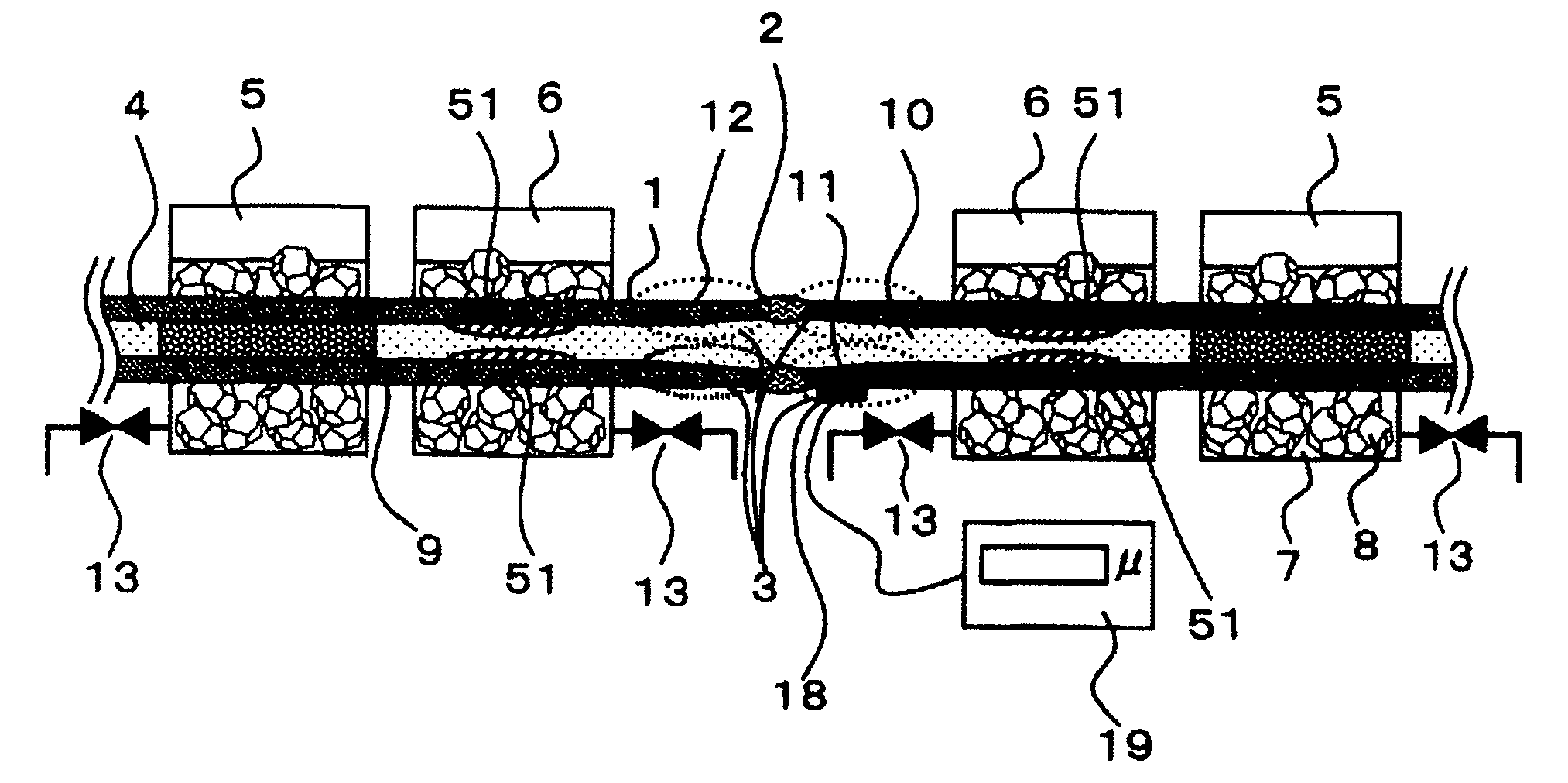
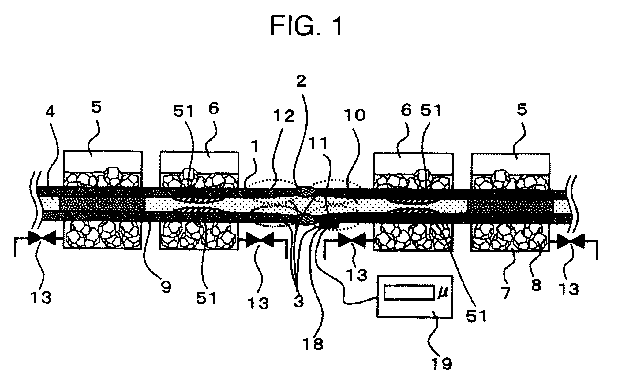
[0026] An execution method according to the present invention will be described with reference to FIG. 1, which converts tensile residual stress on an inner surface of a welded part of a pipe to compressive residual stress, with use of ice plugs formed by cooling the pipe from an outer surface.

[0027]FIG. 1 shows an embodiment of an execution method which is applied to the vicinity of a butt-welded part of a pipe, and includes the steps of: placing refrigerant containers for forming ice plugs in the upstream and downstream of the butt-welded part of the pipe; cooling an outer surface of the pipe to form the ice plugs; and then cooling an outer surface of the pipe with use of at least one refrigerant container for expanding the pipe, which is arranged between the refrigerant containers for forming the ice plugs.

[0028] In the embodiment shown in FIG. 1, there is an edge preparation part 3 with a partially-thin pipe thickness in the vicinity of the butt-welded part 2 of the pipe 1. Th...

embodiment 2

[0036] Another embodiment of an execution method according to the present invention for converting tensile residual stress working on an inner surface of a welded part of a pipe to compressive residual stress with use of an ice plug formed by cooling the pipe from the outer surface will be described with reference to FIG. 3.

[0037]FIG. 3 shows an embodiment of an execution method which is applied to the vicinity of a butt-welded part of a pipe with a large inner diameter, and comprises the steps of: placing refrigerant containers 5 for forming ice plugs in the upstream and downstream of the butt-welded part of the pipe; cooling an outer surface of the pipe to form the ice plugs; and then cooling an outer surface of the pipe with use of at least one refrigerant container 6 for expanding the pipe, which is arranged between the refrigerant containers for forming the ice plugs.

[0038] In the embodiment in FIG. 3, there is an edge preparation part 3 with a partially-thin thickness in the...


PUM

PropertyMeasurementUnit
residual stressaaaaaaaaaa
pressureaaaaaaaaaa
internal pressuresaaaaaaaaaa

Abstract

An method for converting tensile residual stress on an inner surface of a welded part of a pipe to compressive residual stress with use of ice plugs formed by cooling the pipe from the outer surface, comprises the steps of: placing refrigerant containers for forming the ice plugs in the upstream and downstream of a butt-welded part; cooling the outer surface of the pipe to form the ice plugs; and then cooling the outer surface of the pipe with use of at least one refrigerant container for expanding the pipe arranged between the refrigerant containers for forming the ice plugs. When the method is applied to a pipe with a large inside diameter, the method comprises forming the ice plugs at a curved pipe, an elbow or a branch pipe in the upstream and downstream of the butt-welded part.

Description

BACKGROUND OF THE INVENTION [0001] (1) Field of the Invention [0002] The present invention relates to a method for improving residual stress at a welded part of a pipe made of austenitic stainless steel or the like, in which stress corrosion cracking can occur. [0003] (2) Description of Related Art [0004] As an example for reducing residual stress in an inner surface of a pipe, JP-A-2001-150178 discloses that an outer surface of an annular welded part is rapidly heated to decrease tensile residual stress on an inner surface. According to the document, a temperature difference between the inner and outer surfaces of the pipe is introduced by rapid heating of the pipe, so that the residual stress in the inner surface of the pipe, which is a low-temperature side, is improved by using the difference of the thermally expansion between the inner and outer surfaces. [0005] In addition, there is a high-frequency induction heating method for decreasing tensile residual stress in an inner sur...

Claims


Application Information

Patent Timeline
Patent Type & Authority Applications(United States)
IPC IPC(8): F25C1/00F25C1/22B21C37/08B21D26/02B21D26/033B23K31/00B23K101/06
CPCF16L55/103
Inventor AOIKE, SATORUHISATSUNE, MASAKAZU
Owner HITACHI-GE NUCLEAR ENERGY LTD
Why Eureka
Try Eureka