System and method for modulating power signals to control sputtering

a technology of power signal and power supply, applied in the direction of electrolysis components, vacuum evaporation coatings, coatings, etc., can solve the problems of unwanted debris on the substrate, poor quality films, and industry has not yet developed reliable, efficient and commercially practical solutions

Inactive Publication Date: 2006-12-14
APPLIED MATERIALS INC
View PDF69 Cites 367 Cited by
  • Summary
  • Abstract
  • Description
  • Claims
  • Application Information

AI Technical Summary

Benefits of technology

[0016] Exemplary embodiments of the present invention that are shown in the drawings are summarized below. These and other embodiments are more fully described in the Detailed Description section. It is to be understood, however, that there is no intention to limit the invention to the forms described in this Summary of the Invention or in the Detailed Description. One skilled in the art can recognize that there are numerous modifications, equivalents and alternative constructions that fall within the spirit and scope of the invention as expressed in the claims.

Problems solved by technology

Poor-quality films often result from unwanted debris collecting on the substrate and / or from films poorly forming on the substrate.
But the industry has not yet developed reliable, efficient, and commercially practical solutions to its debris and film formation problems for these new thin film requirements.
Debris that comes from the target is often the result of nodules and electrical arcing.
Nodules can cause significant problems—the most serious of which is arcing and debris.
This arc essentially causes the nodule to explode and blow particles toward the substrate creating debris.
Target particles that impact the film can cause three problems.
First, they can disrupt the crystals growing on the film.
In some instances, the impact can cause large scars and craters on the film surface.
Second, the debris from the target can break loose existing film particles—leaving film shadows during the deposition process.
Finally, high temperature debris blown from the target can burn the growing film, especially if it has been grown on a polymer
Even if film growth is not disrupted by debris, films may still not form properly.
A significant problem plaguing film manufactures relates to micro-crystalline quality, nonuniform film growth, and stoichiometry.
The ion source is distinct from the cathode and target, and it is very expensive.
This expense has prevented ion-assisted deposition from being widely adopted.

Method used


Image

  • System and method for modulating power signals to control sputtering
  • System and method for modulating power signals to control sputtering
  • System and method for modulating power signals to control sputtering

Examples


Embodiment Construction

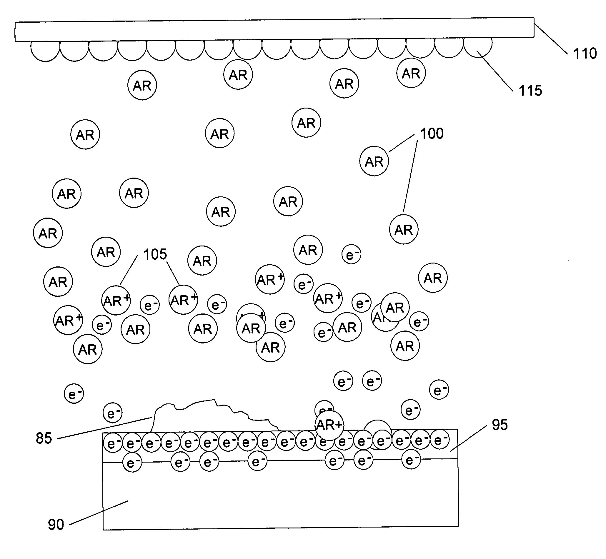
[0046] Referring now to the drawings, where like or similar elements are designated with identical reference numerals throughout the several views, and referring in particular to FIGS. 6A and 6B, they illustrates the arc prevention capabilities of a sputtering system that includes a pulsed-DC power supply. In this illustration, a pulsed-DC power supply (not shown) is used to provide a pulsed-DC signal to the cathode 90.

[0047]FIG. 6B illustrates a pulsed-DC signal corresponding to FIG. 6A. Notice that the stable voltage 120 is around negative 100 volts (−100). At periodic intervals, the power supply reverses the voltage for a short period. For example, the power supply can provide a 3 or 4 microsecond positive pulse 125 to the cathode 90. This positive pulse 125 positively charges the target 95 and the cathode 90. FIG. 6A reflects this charge with the “+” signs on the target 95. Because the Argon ions 105 are also positively charged, they are repelled by the same positive charge on ...


PUM

PropertyMeasurementUnit
voltageaaaaaaaaaa
voltageaaaaaaaaaa
steady-state DC voltageaaaaaaaaaa

Abstract

One embodiment includes a sputtering system that includes a vacuum chamber; a substrate transport system configured to transport a substrate through the vacuum chamber; a cathode for supporting a sputtering target, the cathode at least partially inside the vacuum chamber; and a power supply configured to supply power to the cathode and the power supply configured to output a modulated power signal. Depending upon the implementation, the power supply can be configured to output an amplitude-modulated power signal; a frequency-modulated power signal; a pulse-width power signal; a pulse-position power signal; a pulse-amplitude modulated power signal; or any other type of modulated power or energy signal.

Description

FIELD OF THE INVENTION [0001] The present invention relates to power supplies and systems for sputtering. BACKGROUND OF THE INVENTION [0002] Coated substrates are found almost everywhere and are critical for today's consumer products, solar products, and glass. For example, typical consumer products that utilize coated substrates include cell phone displays, flat-panel computer displays, flat-panel televisions, personal digital assistants, and digital watches. These coated substrates are generally formed by depositing a thin layer of material on a particular substrate. Often, this deposited material is a transparent conductive oxide (TCO), which transmits light and can conduct electrical current. Exemplary TCOs include indium tin oxide (ITO) and aluminum zinc oxide (AZO), but other TCOs are known to those of skill in the art. [0003] Manufacturers use a process known as “sputtering” to deposit TCOs and other films on substrates. Sputtering involves atomizing a target by bombarding it...

Claims


Application Information

Patent Timeline
Patent Type & Authority Applications(United States)
IPC IPC(8): C23C14/00
CPCH01J37/32027H01J37/32036H01J37/34H01J37/32743H01J37/32752H01J37/32137
Inventor STOWELL, MICHAEL W.
Owner APPLIED MATERIALS INC
Why Eureka
Try Eureka