Enhanced electrical machine cooling

a technology for electrical machines and cooling features, applied in the direction of windings, magnetic circuit rotating parts, magnetic circuit shapes/forms/constructions, etc., can solve the problems of system downtime, reducing efficiency, and reducing machine performance, so as to improve heat dissipation and enhanced cooling features

Inactive Publication Date: 2006-12-21
RELIANCE ELECTRIC TECH
View PDF16 Cites 61 Cited by
  • Summary
  • Abstract
  • Description
  • Claims
  • Application Information

AI Technical Summary

Benefits of technology

[0007] In accordance with certain exemplary embodiments, the present technique provides an electrical machine that has enhanced cooling features. The exemplary electrical machine includes a plurality of stator laminations, each stator lamination having a plurality of fins extending radially outward with respect to the stator lamination. When assembled in an electrical machine, the plurality of stator laminations cooperates to define a stator core. Cooling airflow generated by a fan, for example, is routed over the outer peripheral surface of the stator core: The stator fins improving heat dissipation in the electrical machine.

Problems solved by technology

If left unabated, excess heat may degrade the performance of the machine, reducing efficiency, for instance.
Worst yet, excess heat may contribute to any number of malfunctions, leading to system down time and, in certain instances, requiring maintenance and / or replacement.
Undeniably, reduced efficiency and increased malfunctions are undesirable events that may lead to increased costs.
Unfortunately, traditional electrical motors and generators—particularly Totally Enclosed Fan Cooled (TEFC) assemblies—house the stator core within a frame assembly, placing an intermediate structure between the stator core and the surrounding environment and, thus, decreasing the efficacy of applied convective cooling techniques.
Because it is an intermediate structure, this frame retards the efficacy of the cooling airflow with respect to the stator core.

Method used


Image

  • Enhanced electrical machine cooling
  • Enhanced electrical machine cooling
  • Enhanced electrical machine cooling

Examples


Embodiment Construction

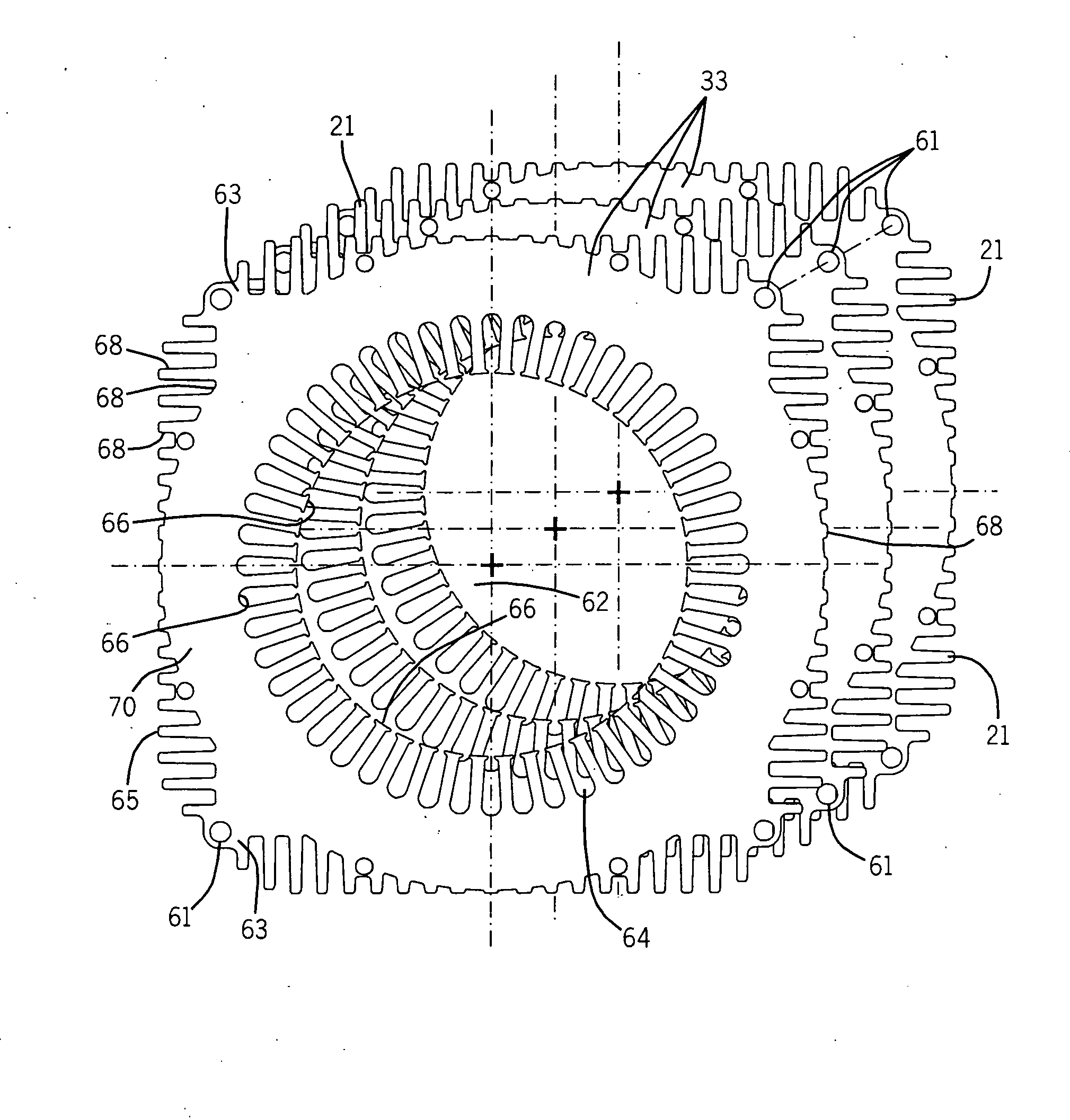
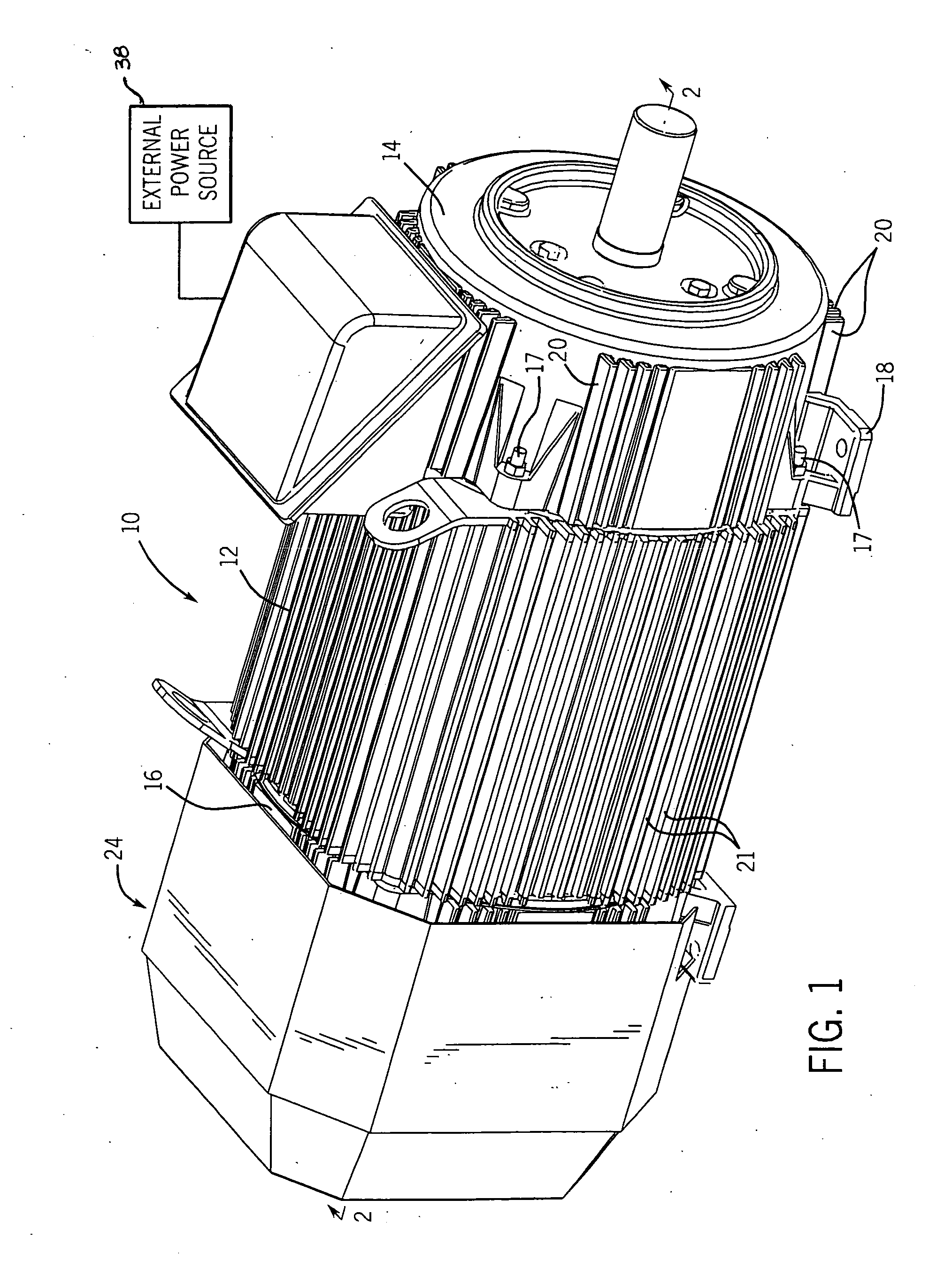
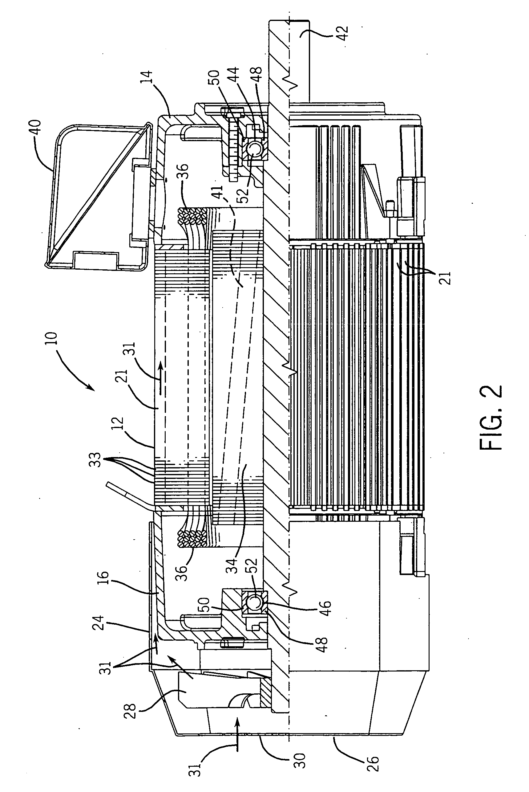
[0014] Turning the figures, FIGS. 1 and 2 illustrate an exemplary electrical machine 10. As illustrated, the exemplary electrical machine 10 is envisaged as an induction motor. However, it is worth noting that the present technique is applicable to any number of electrical machines, including electrical motors and electrical generators. Moreover, although the following discussion focuses on induction devices, the present technique is equally applicable to direct current (dc) devices as well as permanent magnet (pm) devices. For example, devices in which the rotor's magnetic flux is produced as a result of the material employed—and not by induction—also benefit from the present technique.

[0015] The exemplary machine 10 includes a stator core 12 capped at opposite ends by drive-end and opposite drive-end endcaps 14 and 16, respectively. Advantageously, the exemplary endcaps 14 and 16 include mounting and transportation features, such as the mounting flanges 18, as well as heat dissip...


PUM


Abstract

In one embodiment, the present technique relates to a motor having enhanced cooling. The exemplary motor includes a stator core that is formed of a plurality of stator laminations and that is, at least partially, a peripheral surface of the motor. Each stator lamination has a plurality of fins that extend radially outward. When assembled, the fins of adjacent laminations cooperate to form larger fins extending the length of the stator core. These fins enhance the cooling of the motor, by improving heat dissipation of the motor.

Description

BACKGROUND [0001] The present technique relates generally to the field of electrical machines, which includes electrical motors and generators. More particularly, the present technique relates to the dissipation of heat in such electrical machines. [0002] Electrical machines, such a motors and generators, are commonly found in industrial, commercial, and consumer settings. In industry, such machines are employed to drive various kinds of devices, including pumps, conveyors, compressors, fans, and so forth, to mention only a few. In the case of electric motors and generators, these devices generally include a stator, comprising a multiplicity of stator windings, surrounding a rotor. [0003] By establishing an electromagnetic relationship between the rotor and the stator, electrical energy can be converted into kinetic energy, and vice-versa. In the case of alternating current (ac) motors, ac power applied to the stator windings effectuates rotation of the rotor. The speed of this rota...

Claims


Application Information

Patent Timeline
Patent Type & Authority Applications(United States)
IPC IPC(8): H02K9/00H02K3/24
CPCH02K1/16H02K9/14H02K5/18H02K1/20
Inventor EVON, STEVE T.MARTIN, WILLIAM E.
Owner RELIANCE ELECTRIC TECH
Why Eureka
Try Eureka