Femtosecond laser micromachining of a contact lens and a contact lens manufactured thereby

a technology of micro-machining and contact lenses, which is applied in the field of manufacturing contact lenses, can solve the problems of discomfort in wearing contact lenses, the damage of the contact lens area, and the description apparatus has not gained commercial popularity, and achieves the effect of reducing heat-related damag

Inactive Publication Date: 2006-12-21
BAUSCH & LOMB INC
View PDF15 Cites 46 Cited by
  • Summary
  • Abstract
  • Description
  • Claims
  • Application Information

AI Technical Summary

Benefits of technology

[0011] Another advantage of the invention is in providing such a method in which the features are provided in the contact lens with minimal heat related damage to the surrounding regions of the contact lens.
[0012] These and other advantages are provided by a method of providing a feature on a contact lens in accordance with the invention. In particular, the method comprises applying a femtosecond laser beam to the contact lens to ablate at least a portion of the contact lens to provide the feature on the contact lens. In this regard, the contact lens may be located in a fixture. The invention may be used to provide features on a contact lens made of elastomeric silicone, rigid silicone, or other contact lens material.
[0013] In accordance with one embodiment of the method of the invention, the femtosecond laser beam has a pulse width between 10×10−15 seconds and 200×10−15 seconds, and preferably, between 60×10−15 seconds and 100×10−15 seconds. In another embodiment, the femtosecond laser beam has a wavelength between 100 nm and 1500 nm, and preferably, between 266 nm and 1060 nm.
[0014] Ablating of the contact lens by the laser beam may include cutting, melting and / or vaporizing a portion of the contact lens, and is attained without measurably increasing the temperature of a surrounding area of the contact lens. The method of the invention may be used to provide any appropriate feature on the contact lens. For example, the method may be used to provide fenestrations, channels, and / or angulations on the contact lens, or used to form the peripheral edge of the contact lens.
[0015] In one embodiment, the feature provided is a fenestration that extends though the contact lens between an anterior surface of the contact lens and a posterior surface of the contact lens. The fenestration may be any desired size. For example, the invention may be used to provide a fenestration having a diameter between 4 μm and 24 μm, and preferably between 8 μm and 12 μm. The fenestration may have a diameter at the anterior surface of the contact lens that is different than a diameter at the posterior surface.
[0016] In accordance with another aspect of the invention, a method of manufacturing a contact lens is provided comprising locating a contact lens in a fixture, and applying the femtosecond laser beam to the located contact lens to ablate at least a portion of the contact lens. In one implementation, the femtosecond laser beam has a pulse width between 60×10−15 seconds and 100×10−15 seconds, and has a wavelength between 266 nm and 1060 nm. The present method may be used to form a fenestration having a diameter between 8 μm and 12 μm.

Problems solved by technology

However, the described apparatuses have not gained in commercial popularity due to the fact that the concentrated laser also causes the surrounding areas of the contact lens to be damaged from the heat of the laser.
Such edges, burrs, or particles of removed material can cause discomfort to the wear of the contact lens.
However, excimer lasers, while being superior to conventional methods, have also been found to be inadequate in providing fenestrations.
In particular, even when excimer lasers such as that disclosed in Seden et al. is used to provide fenestrations on a contact lens, minor heat related damage to the surrounding regions of the contact lens results which may negatively impact the performance of the contact lens.
Therefore, there still exists an unfulfilled need for a method for laser micromachining contact lenses to provide features such as fenestrations thereon, with minimal heat related damage to the surrounding regions of the contact lens.

Method used


Image

  • Femtosecond laser micromachining of a contact lens and a contact lens manufactured thereby
  • Femtosecond laser micromachining of a contact lens and a contact lens manufactured thereby

Examples


Embodiment Construction

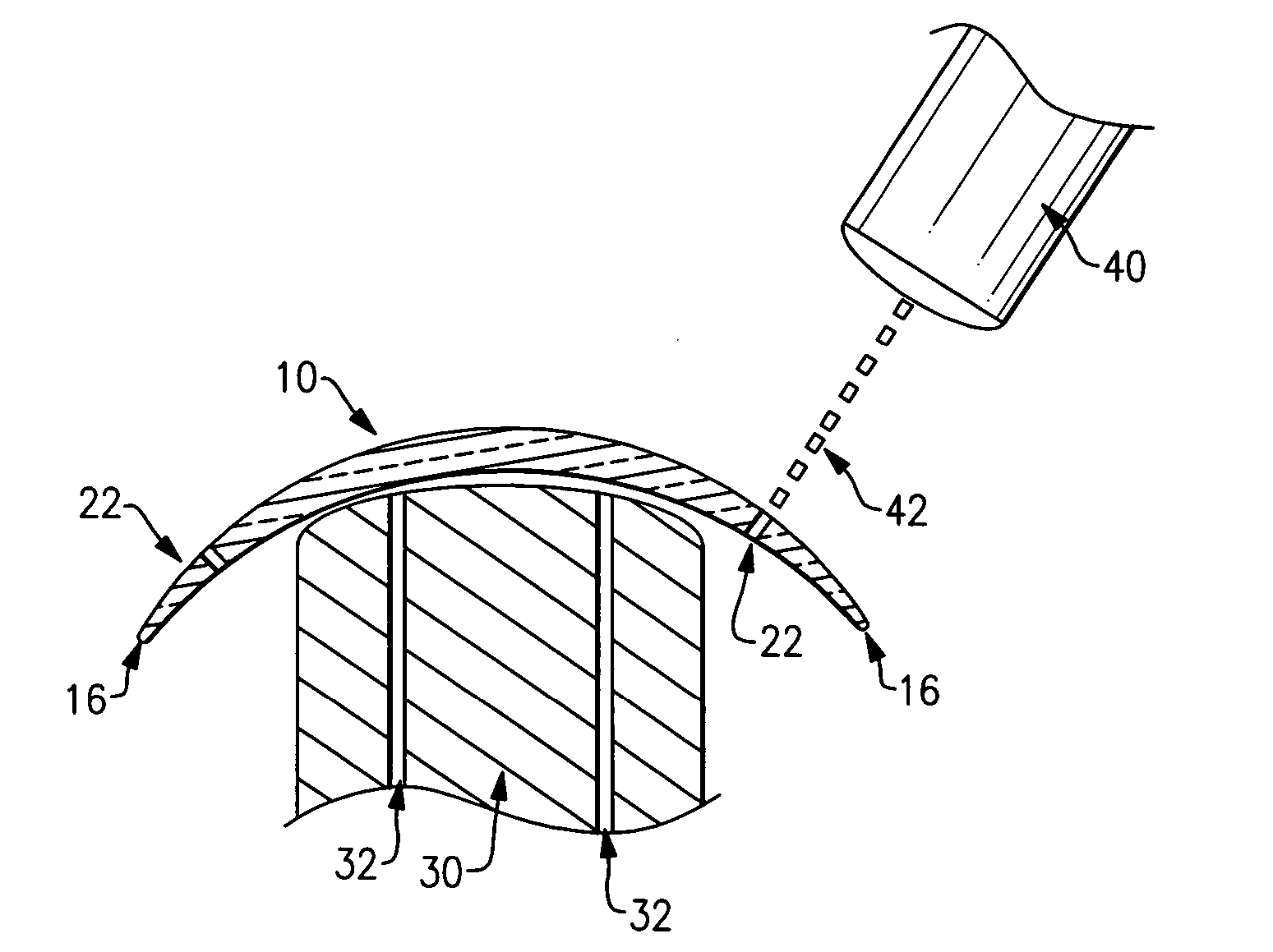
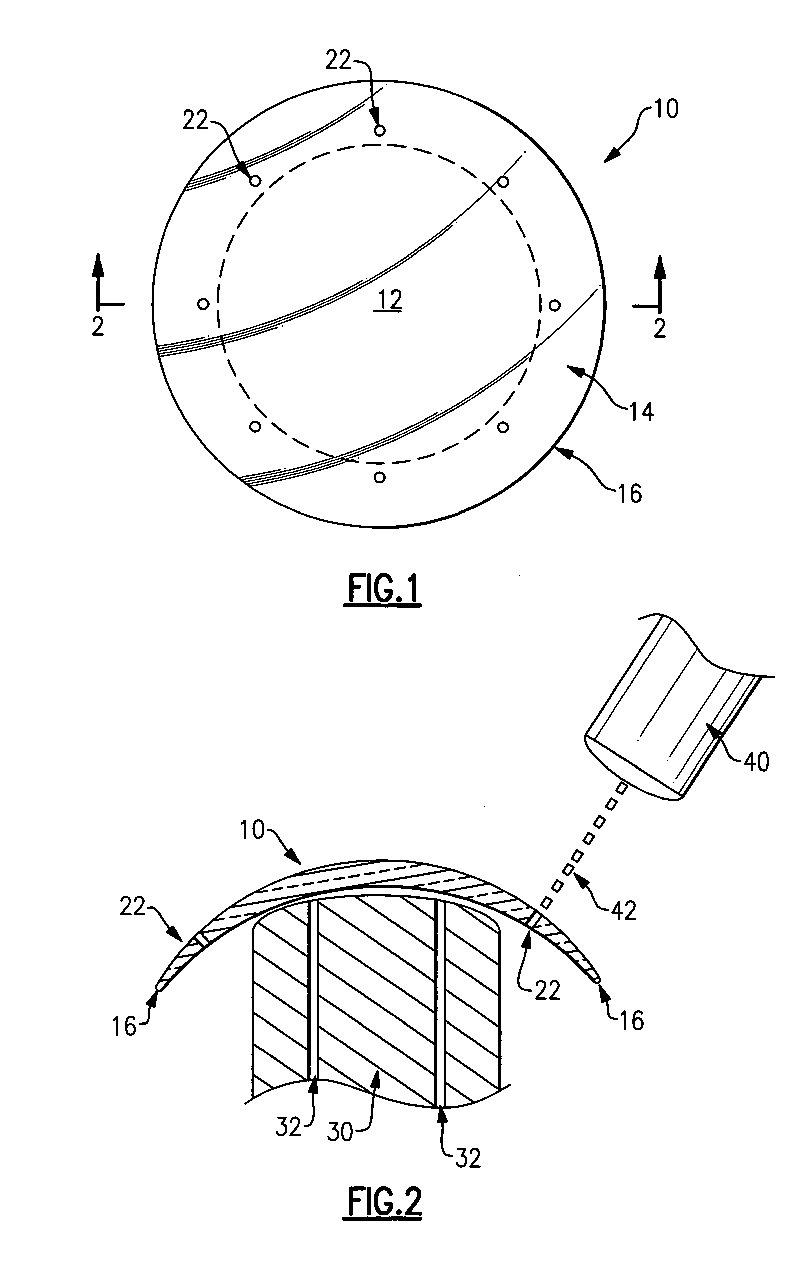
[0020]FIG. 1 shows an anterior end view of a contact lens 10 suitable for being manufactured using the method in accordance with the invention. FIG. 2 is an enlarged cross-sectional view of the contact lens 10 of FIG. 1 as viewed along 2-2 being manufactured using the method of the invention. As explained below, an advantage of the invention is in providing a method for laser micromachining contact lens 10 to provide various features thereon. In this regard, the invention allows provision of features such as fenestrations, channels, and / or angulations on the contact lens 10 that are substantially free of heat related damage to the surrounding regions. Of course, the method of the invention may be used to provide different features on the contact lens, for example, to manufacture the peripheral edge of the contact lens.

[0021] As shown in FIGS. 1 and 2, the illustrated example contact lens 10 includes a central portion 12 that covers the cornea of the wearer of the contact lens 10 to...


PUM

PropertyMeasurementUnit
wavelengthaaaaaaaaaa

Abstract

A method of providing a feature on a contact lens including applying a femtosecond laser beam to ablate at least a portion of the contact lens to provide the feature on the contact lens. In one embodiment, the femtosecond laser beam has a pulse width between 10×10−15 seconds and 200×10−15 seconds, and has a wavelength between 100 nm and 1500 nm. A contact lens is also provided including at least one fenestration fluidically connecting the anterior surface and the posterior surface, the fenestration being formed using a femtosecond laser in a manner that areas surrounding the fenestration are substantially free of heat damage.

Description

BACKGROUND OF THE INVENTION [0001] 1. Field of the Invention [0002] The invention is directed to a method for manufacturing contact lenses. In particular, the invention is directed to a method for laser micromachining contact lenses to provide features thereon. In addition, the invention is also directed to a contact lens manufactured in accordance with the method. [0003] 2. Description of Related Art [0004] Contact lenses have been commonly used by individuals to correct their eyesight for many years. Various contact lenses are available to consumers including daily wear and extended wear soft contact lenses, as well as hard contact lenses. Contact lenses include a lens body with an anterior surface, and a posterior surface that contacts the surface of the eye. It is also known to provide fenestrations on the contact lenses. The fenestrations define openings which extend through the lens body to provide pathway for fresh, oxygenated tears to flow to the surface of the eye to enhanc...

Claims


Application Information

Patent Timeline
Patent Type & Authority Applications(United States)
IPC IPC(8): G02C7/04
CPCB23K26/0635B23K26/385B23K26/367B23K26/0624B23K26/364B23K26/389
Inventor ERICKSON, PAUL M.KUNZLER, JAY F.SALAMONE, JOSEPH C.
Owner BAUSCH & LOMB INC
Why Eureka
Try Eureka