Digesters

a technology of digesters and complex molecules, applied in the field of digesters, can solve the problems of long residence time typically required to digest organic waste, limited use of digesting for municipal or industrial waste, and complex molecules hydrolysis rate limitation, etc., and achieve the effect of speeding up the start-up or maintenan

Inactive Publication Date: 2006-12-28
TOLBERT & ASSOCS
View PDF23 Cites 67 Cited by
  • Summary
  • Abstract
  • Description
  • Claims
  • Application Information

AI Technical Summary

Problems solved by technology

The main disadvantage of anaerobic digesters is the long residence time typically required to digest organic waste.
Although these batch digesters can handle large quantities of waste, the prolonged time usually required for digestion has limited their use for municipal or industrial waste.
In many digesters, the rate-limiting step is the hydrolysis of complex molecules, particularly the polysaccharides.
Two important limitations of digesters are the rate at which waste can be processed, and the fraction of solids in the waste that can be digested.
However, the UASB is only useful with wastes containing low amounts of solids, typically less than 1%.
The product may be miscible or immiscible in water.
Biopharmaceutical fermentations tend to be very complex systems, with many potentially important control parameters.

Method used


Image

  • Digesters
  • Digesters
  • Digesters

Examples


first embodiment

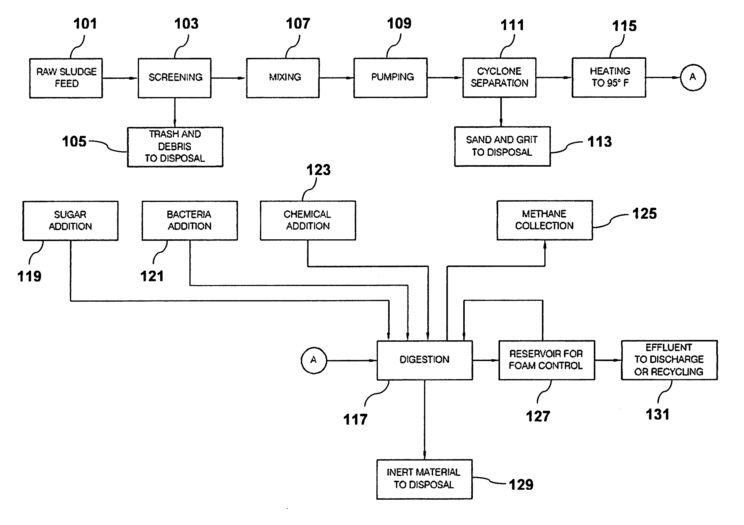
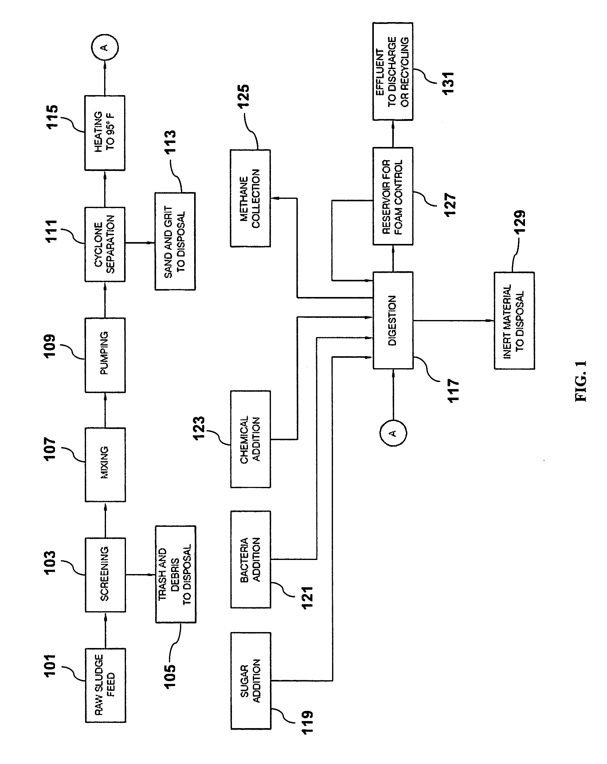
[0081] In a four reaction chambered anaerobic digester in accordance with the present invention, the multichambered digester provides a series of environments that select for anaerobic microorganisms that efficiently digest wastewater sludge. Under most operating conditions, no microorganisms will have to be added above those naturally found in the sludge. However if organic waste is from an industrial source, such as a poultry processing plant, a mixed population of aerobic or anaerobic microorganisms may need to be added initially.

second embodiment

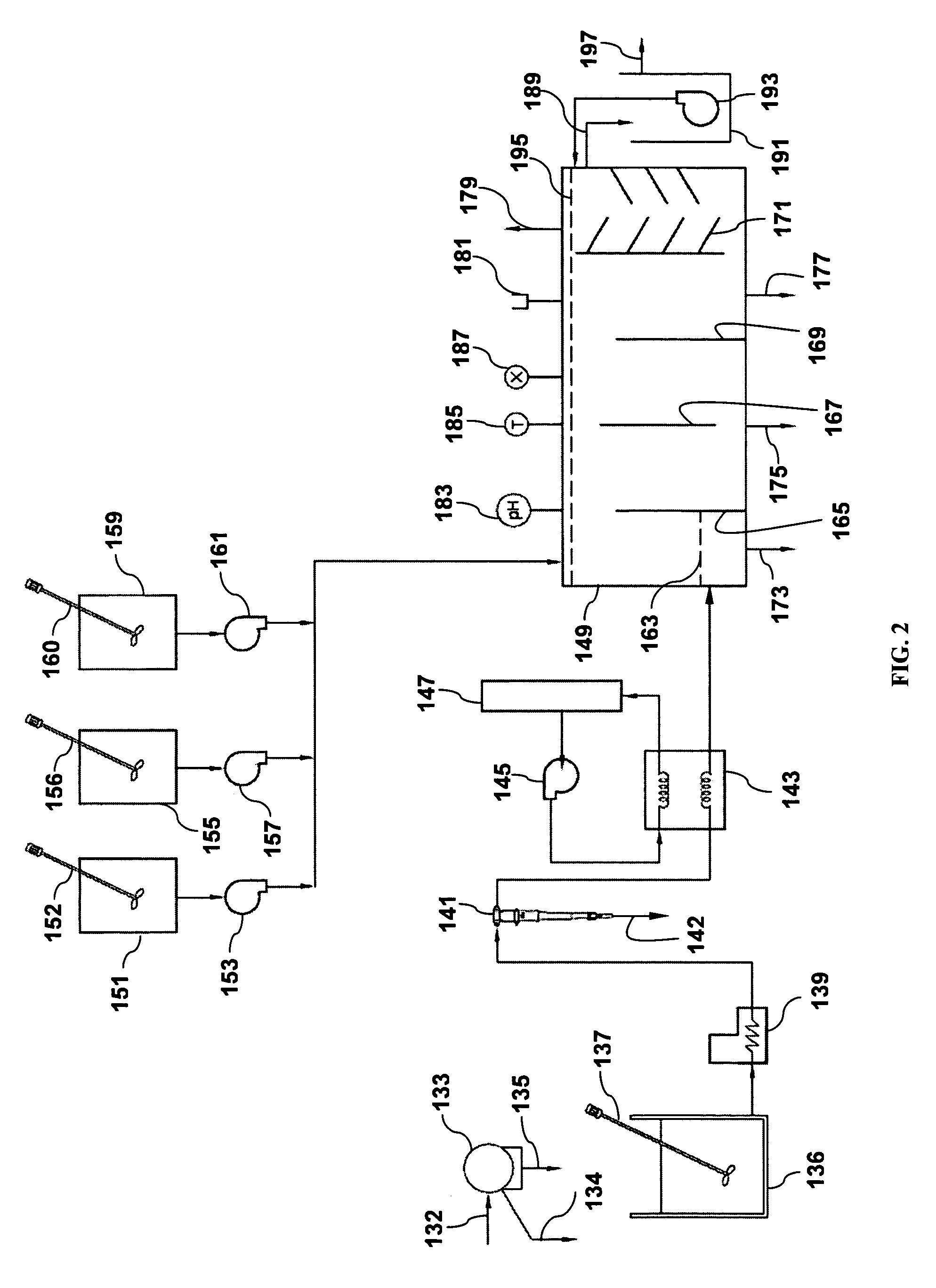
[0082] The organic waste is supplemented with nutrients, examples of which are sugar and trace elements, from a nutrient tank, which is in fluid connection with the waste influent that is in fluid connection with one or more reaction chambers of the digester. In a multichambered anaerobic digester, the multichambered digester provides a series of environments that select anaerobic microorganisms that efficiently digest wastewater sludges. The organic waste flows into a collecting tank. A fraction of the volume contained in the collecting tank is continuously pumped through a controllable temperature control device that controls the temperature of the organic waste, one example of which is a heat exchanger. The organic waste, now at a controllable temperature, is supplemented with nutrients, one example of which is sugar, from a nutrient tank, which is in fluid connection with the waste influent that is in fluid connection with one or more reaction chambers of the digester. The organ...

third embodiment

[0083] In a multichambered anaerobic digester, the multichambered digester provides a series of environments that select for anaerobic microorganisms that efficiently digest wastewater sludges. The organic waste influent is collected in a holding tank. The solid concentration may be adjusted in this chamber. The organic waste after solid concentration adjustment is in fluid connection with a collection tank. A fraction of the volume contained in the collection tank is continuously pumped through a device or devices for removing inorganic solids, such as a rotating drum screen or a centrifugal separator or cyclone, which are positioned upstream of the first reaction chamber. A fraction of the volume contained in the collection tank is continuously pumped through a controllable temperature control device that controls the temperature of the organic waste, one example of which is a heat exchanger. The organic waste, now at a controllable temperature, is supplemented with nutrients, or ...


PUM

PropertyMeasurementUnit
widthaaaaaaaaaa
residence timeaaaaaaaaaa

Abstract

Methods and devices are disclosed for converting predominantly organic waste materials, such as sludge, into useful byproducts.

Description

[0001] This application claims the benefit of priority to U.S. Provisional Patent Application No. 60 / 680,987 filed on May 13, 2005, which is hereby incorporated by reference in its entirety.BACKGROUND [0002] 1. Field [0003] The present invention relates to methods and devices for converting predominantly organic waste materials, such as animal waste, into useful byproducts. [0004] 2. Description of Related Art [0005] Various designs of digesters exist for the processing and treatment of primarily organic wastes (solids, semi-solids, and liquids) to produce non-hazardous, and sometimes beneficial, products for release to the environment. Digesters may be designed for use in low technology rural areas or for sophisticated industrial areas. Many types of organic wastes (i.e., municipal, industrial, agricultural, and domestic wastes) maybe treated by anaerobic digestion. See F. R. Hawkes et al., “Chapter 12: Anaerobic Digestion,” in Basic Biotechnology (J. Bu'Lock and B. Kristiansen, ed...

Claims


Application Information

Patent Timeline
Patent Type & Authority Applications(United States)
IPC IPC(8): C02F11/04C02F11/121
CPCC02F3/348Y02E50/343C02F11/121C02F2103/20C02F2209/005C02F2209/02C02F2209/06C02F2305/06C05F17/0018C05F17/0027C12M21/04C12M23/34C12M23/58C12M41/26C12M45/04C12P3/00C12P5/023C02F11/04Y02P20/145C05F17/40C05F17/50Y02E50/30Y02W30/40
Inventor BURNETT, CLYDE H.TOLBERT, VERN L.
Owner TOLBERT & ASSOCS
Why Eureka
Try Eureka