Mass spectrometer

a mass spectrometer and mass spectrometer technology, applied in the direction of isotope separation, electric discharge tube, particle separator tube, etc., can solve the problems of reduced sensitivity, reduced ion detection sensitivity and/or ion selectivity, and reduced accumulation efficiency, etc., to achieve high ion selectivity and high sensitivity analysis

Active Publication Date: 2006-12-28
HITACHI HIGH-TECH CORP
View PDF11 Cites 21 Cited by
  • Summary
  • Abstract
  • Description
  • Claims
  • Application Information

AI Technical Summary

Benefits of technology

[0014] With respect to the mass spectrometer using the ion trap, it is important to realize high-sensitivity analysis and high ion selectivity.

Problems solved by technology

In the case of the methods in the patent documents 1 to 6, it may occur sometimes that the effect of the space charge caused by increase of ion content accumulated in the ion trap results in decreased efficiency of accumulation, isolation, dissociation, and ejection, and non-intentionally affects other ions outside the target mass range, which lowers in ion detection sensitivity and / or ion selectivity.
The method of the patent document 7 controls the ion introduction amount by shortening the time for accumulation of ions into the ion trap, but this will result in decreased sensitivity.

Method used


Image

  • Mass spectrometer
  • Mass spectrometer
  • Mass spectrometer

Examples


first embodiment

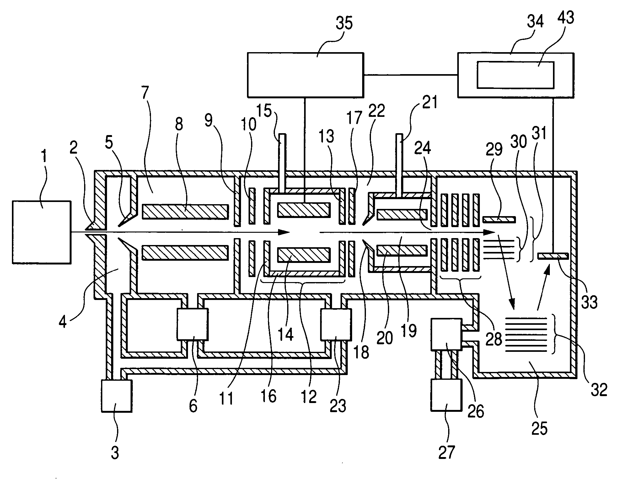
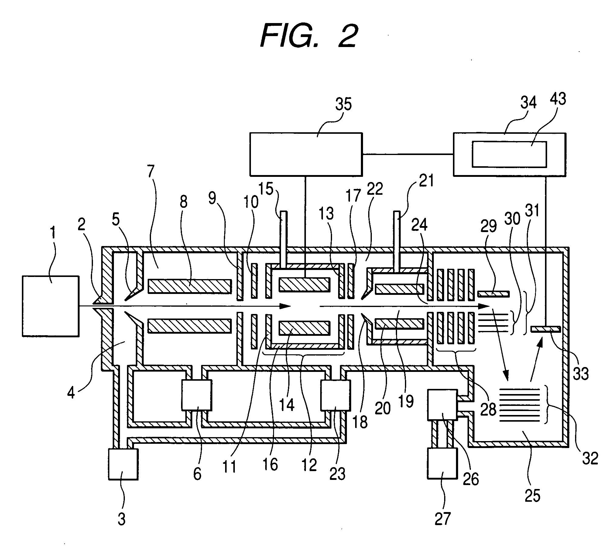
[0033]FIG. 2 is a block diagram illustrating the quadrupole linear ion trap time-of-flight mass spectrometer according to the present invention.

[0034] Ions produced in the ion source 1 are moved through the aperture 2 and introduced into the first differential pumping region 4 where exhaust is made to maintain 100-500 Pa by the rotary pump 3. Then, ions are moved through the aperture 5 and introduced into the second differential pumping region 7 where exhaust is effected by the turbo molecular pump 6. The second differential pumping region 7 is provided with the multipole electrode 8 and is maintained at a pressure of about 0.3-3 Pa. To the multipole electrode 8, an alternately phase-reversing frequency of about 1 MHz and a RF voltage with voltage amplitude of several hundred volts are applied. Ions are converged to near the center axis within the multipole electrode 8 for highly efficient transport.

[0035] The ions converged in the multipole electrode 8 are led through the apertur...

second embodiment

[0069]FIG. 12 shows a block diagram of the quadrupole linear ion trap mass spectrometer according to the present invention.

[0070] The ions produced in the ion source 1 are led through the aperture 2 into the first differential pumping region 4 from which air is exhausted by the rotary pump 3 to a pressure of about 100-500 Pa. Then, the ions proceed through the aperture 5 and into the second differential pumping region 7 which is exhausted by the turbo molecular pump 6. The second differential pumping region 7 is provided with the multipole electrode 8 and is maintained at a pressure of about 0.3-3 Pa. To the multipole electrode 8, the alternately phase-reversing frequency of about 1 MHz and the RF voltage with the voltage amplitude of several hundred volts are applied. In the multipole electrode 8, the ions are converged to around the center axis for highly efficient transport.

[0071] The ions converged by the multipole electrode 8 are led through the aperture 9, and the holes of t...

third embodiment

[0084] In a similar configuration to what is shown in FIG. 12, an embodiment or the third embodiment which employs a system different from the second embodiment is explained by using the operational sequence diagram of FIG. 15. The operational sequence diagram of FIG. 15 represents the performance of MS2 analysis. In MS2 analysis, the linear ion trap 12 conducts ion accumulation and ejection in the advance analysis process; conducts ion accumulation and ejection in MS1 analysis, viz., the first mass spectrometry process; and further conducts ion accumulation, isolation, dissociation, and ejection in MS2 analysis, viz., the second mass analysis process. What is different from the operational sequence diagram of FIG. 13 is that no advance analysis exists.

[0085] As explained for the second embodiment, in the ion ejection period, the mass spectrometry is conducted by scanning of the RF voltage and the supplemental AC voltage. Under the influence of space charge that may be caused there...


PUM


Abstract

A mass spectrometer capable of realizing a high-sensitivity ion analysis and a high ion selectivity performance. The mass spectrometer includes the ion source where ions are produced, the ion trap where ions are accumulated, isolated, dissociated, and ejected, the detector to detect ions to be detected, and the controller to control operations of the ion trap. It has the features that the total ion accumulation in or just before each period is calculated based on the result obtained from the mass spectrometry in the preceding period, and that in at least one out of all periods, the condition of voltage applied to the ion trap is corrected depending on the total ion accumulation. Compared to the related art, the mass spectrometer of the present invention provides much improved performance in analysis sensitivity and ion selectivity.

Description

CLAIM OF PRIORITY [0001] The present application claims priority from Japanese application JP 2005-164962 filed on Jun. 6, 2005, the content of which is hereby incorporated by reference into this application. FIELD OF THE INVENTION [0002] This invention relates to a mass spectrometer using an ion trap, and more particularly, to a mass spectrometer that can realize a high-sensitivity analysis of ion and a high ion selectivity by means of such ion trap. BACKGROUND OF THE INVENTION [0003] When a mass spectrometer is used for the purpose of proteome analysis, the MSn spectrometry that conducts mass spectrometry over multiple stages becomes important. [0004] As a mass spectrometry method that makes MSn spectrometry possible, there is a three-dimensional quadrupole ion trap mass spectrometer. As disclosed in the patent document 1 (U.S. Pat. No. 2,939,952), the three-dimensional quadrupole ion trap is able to stably accumulate ions having a specific mass-to-charge ratio in the ion trap by ...

Claims


Application Information

Patent Timeline
Patent Type & Authority Applications(United States)
IPC IPC(8): H01J49/00
CPCH01J49/4265H01J49/4225
Inventor HASEGAWA, HIDEKIHASHIMOTO, YUICHIROWAKI, IZUMI
Owner HITACHI HIGH-TECH CORP
Why Eureka
Try Eureka