Particle detector for secondary ions and direct and or indirect secondary electrons

a particle detector and electron detector technology, applied in the field of secondary electron detection, can solve the problems of low or no detection efficiency of secondary electrons, inefficient etd collecting grid, and ineffective etd for back scattered electrons (bse)

Active Publication Date: 2006-12-28
EL MUL TECH
View PDF12 Cites 30 Cited by
  • Summary
  • Abstract
  • Description
  • Claims
  • Application Information

AI Technical Summary

Benefits of technology

[0013] a sparse collecting electrode; Venetian Blind strips for converting secondary ions to electrons, said Venetian Blind strips comprising a conducting material and being disposed behind the sparse collecting electrode; at least one further electrode adjacent the Venetian Blind strips, wherein said at least one further electrode enhances the detection efficiency of the particle detector; a scintillating disc for producing scintillation photons upon impingement of energetic electrons, said scintillating disc being biasable with respect to said Venetian Blind strips and said at least one further electrode, respectively; and a light-guide for guiding scintillation photons to a photo-multiplier, wherein the particle detector detects any of the type of the incoming particles, and excludes the other types by switching appropriate voltages on the electrodes.

Problems solved by technology

However, the ETD is not a very effective for back scattered electrons (BSE), defined as electrons emitted from the sample at energies between 50 eV and the beam energy.
Therefore the ETD collecting grid is inefficient in attracting these electrons and leading them to the scintillator.
The drawback of the ETD when used in this ion mode is very low or no efficiency for detecting secondary ions due to the very low luminosity response of any scintillator to impinging ions relative to same energy electrons, compounded by the ions high or total energy loss in the conducting aluminum layer of the scintillating plate.
Multiple detectors increase system cost and occupy place in the vacuum system, which may be needed for sample manipulations.

Method used


Image

  • Particle detector for secondary ions and direct and or indirect secondary electrons
  • Particle detector for secondary ions and direct and or indirect secondary electrons
  • Particle detector for secondary ions and direct and or indirect secondary electrons

Examples


Embodiment Construction

[0046] The invention is now described with reference to the embodiments shown in the drawings which show:

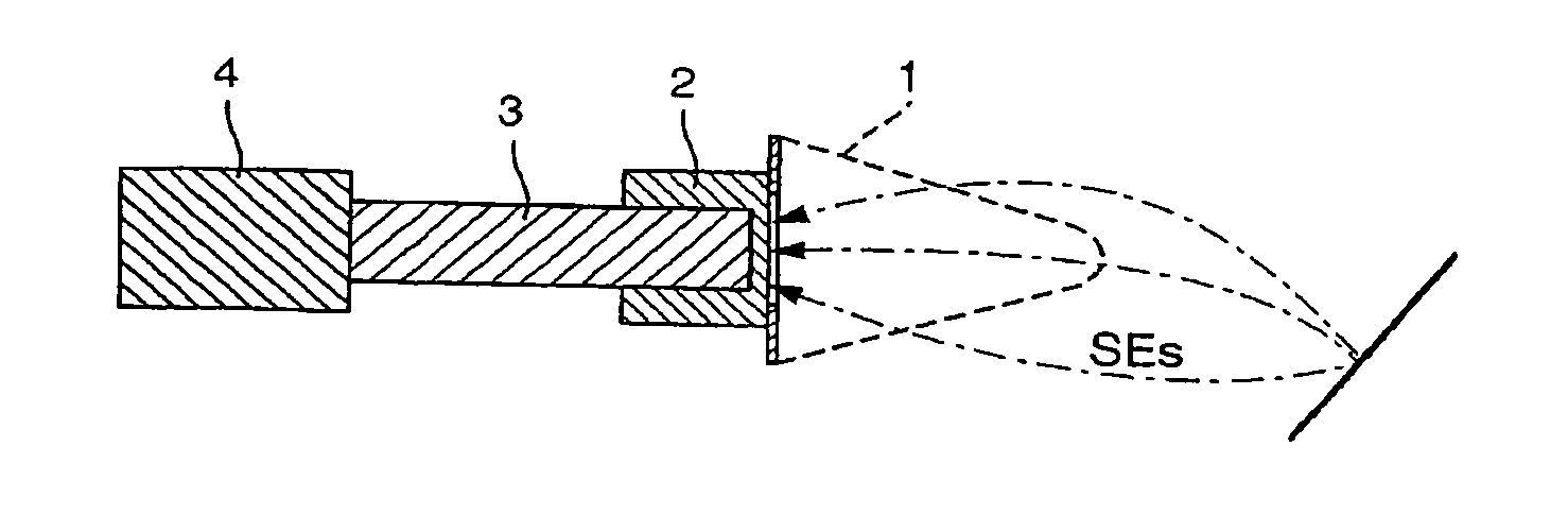
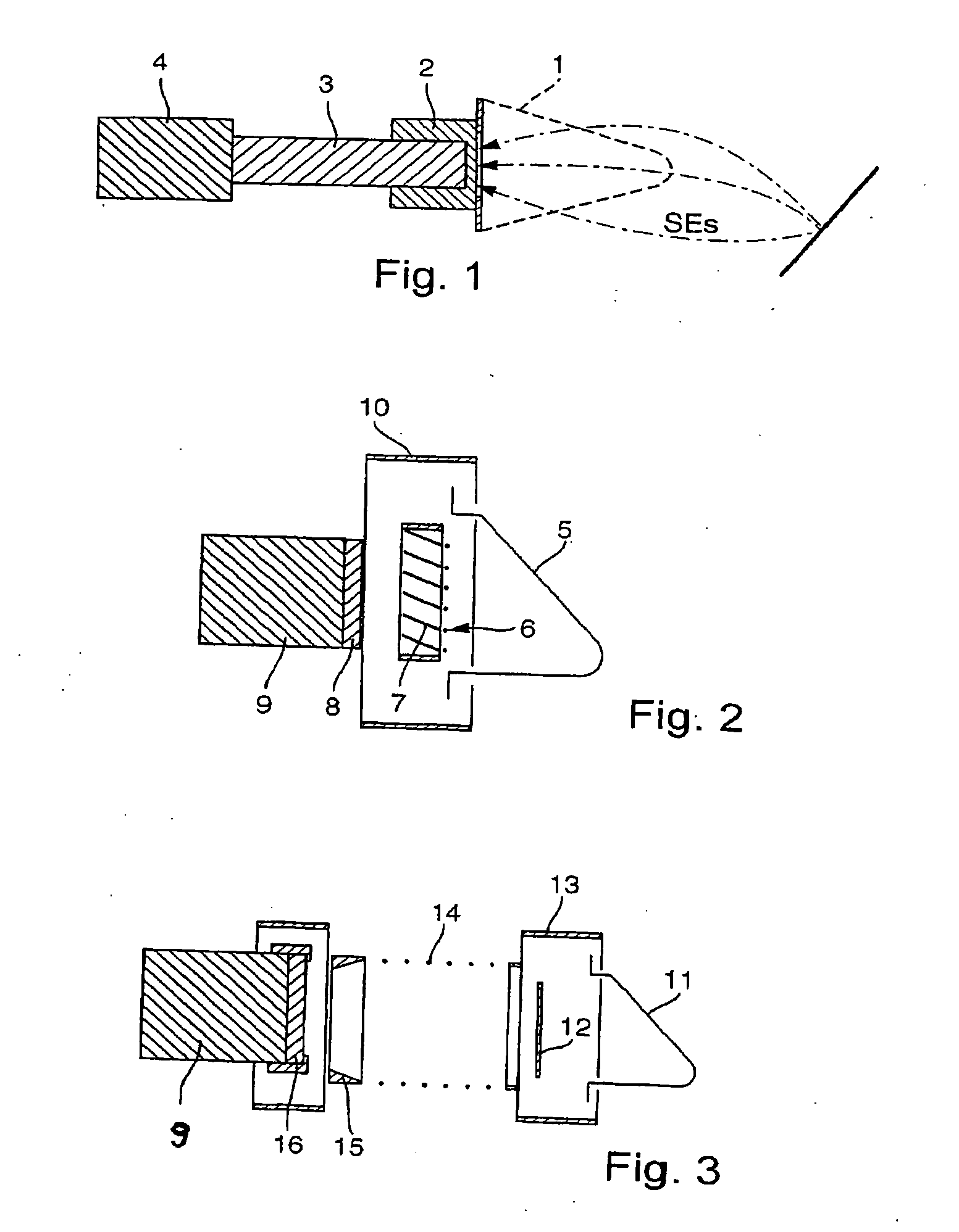
[0047]FIG. 1: a schematic view of ETD detector (prior art).

[0048]FIG. 2: a schematic cross section of low energy electrons or low energy ions detector

[0049]FIG. 3: a cross section of a direct SE and SE3 detector for electron beam systems such as SEM

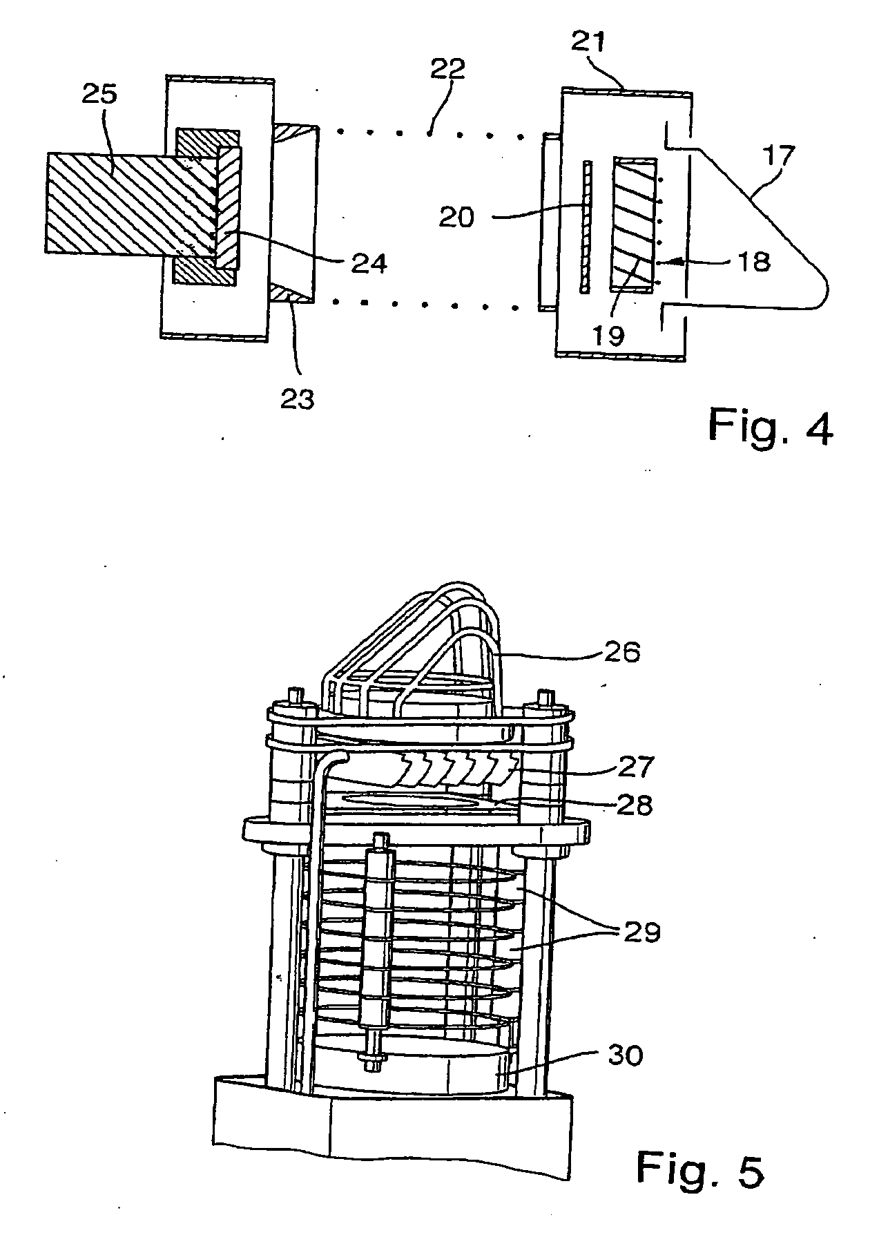
[0050]FIG. 4: a cross section of EISE3 detector with options determined by electrode voltages to measure: Secondary electrons, or low energy secondary ions, or SE3 generated by BSE that hit various parts of the test chamber.

[0051]FIG. 5: an isometric side view of EISE3 detector

[0052]FIG. 6: one half of EISE3 detector in isometric view. The absent part is a mirror image of the shown structure.

[0053]FIG. 7: simulation calculations of SE with tilted collecting sparse grid at +400 V, Venetian Blind strips at +400 V, and phosphor screen at +10 kV. The trajectories have various initial electron energies 1) −2 eV, 2) −5 eV, 3) −10 eV, ...


PUM

PropertyMeasurementUnit
angleaaaaaaaaaa
voltagesaaaaaaaaaa
voltageaaaaaaaaaa

Abstract

A multi-purpose efficient charge particle detector that by switching bias voltages measures either secondary ions, or secondary electrons (SE) from a sample, or secondary electrons that originate from back scattered electrons (SE3), is described. The basic version of the detector structure and two stripped down versions enable its use for the following detection combinations: 1. The major version is for measuring secondary ions, or secondary electrons from the sample, or secondary electrons due to back-scattered electrons that hit parts other than the sample together or without secondary electrons from the sample. 2. Measuring secondary ions or secondary electrons from the sample (no SE3). 3. Measuring secondary electrons from the sample and / or secondary electrons resulting from back-scattered electrons hitting objects other than the sample (no ions).

Description

FIELD OF THE INVENTION [0001] The present invention relates to detecting secondary ions or secondary electrons produced by analytic or surface modification instruments such as Scanning Electron Microscopes (SEM), Focused Ion Beams (FIB), Scanning Auger instruments, Electron Beam Writing machines, etc. In these instruments surface properties in the form of images are obtained by measuring the current of secondary or reflected particles released or produced by a scanning particle beam. BACKGROUND [0002] Almost all SEMs use an ETD (Everhardt Thornley Detector T. E. Everhart and R. F. M. Thornley “Wideband detector for microampere low-energy electron currents. J. Sci. Instr. 37, 246-248 (1960)) to measure the current of secondary electrons (SE) produced by the scanning of the electron beam on a sample. Relating the number of secondary electrons accumulated in a certain time bin to the location bombarded by the scanning beam at that time bin forms the image of the surface topography and ...

Claims


Application Information

Patent Timeline
Patent Type & Authority Applications(United States)
IPC IPC(8): G01N23/00
CPCG01N23/2251H01J37/244H01J37/28H01J2237/31749H01J43/24H01J2237/2448H01J2237/2449H01J43/22
Inventor SCHON, ARMINCHEIFETZ, ELISHOFMAN, SEMYON
Owner EL MUL TECH
Why Eureka
Try Eureka