Video signal transmission method and video processing system

Active Publication Date: 2006-12-28
MAXELL HLDG LTD
View PDF5 Cites 61 Cited by
  • Summary
  • Abstract
  • Description
  • Claims
  • Application Information

AI Technical Summary

Benefits of technology

[0012] In order to accomplish the above objects, the present invention is characterized in that a received compressed video signal is decoded in order to produce a non-compressed video signal, that the compressed video signal is combined with a blanking signal contained in the non-compressed video signal, and that the resultant video signal is transmitted. Moreover, the present invention is characterized in that a compressed video signal that is packetized is combined with a non-compressed video signal that includes synchronizing (hereinafter sync) sign

Problems solved by technology

In other words, it is hard to implement the transmission system described in Patent Document 1 in a television for general home use because the non-compressed video

Method used


Image

  • Video signal transmission method and video processing system
  • Video signal transmission method and video processing system
  • Video signal transmission method and video processing system

Examples


Example

First Embodiment

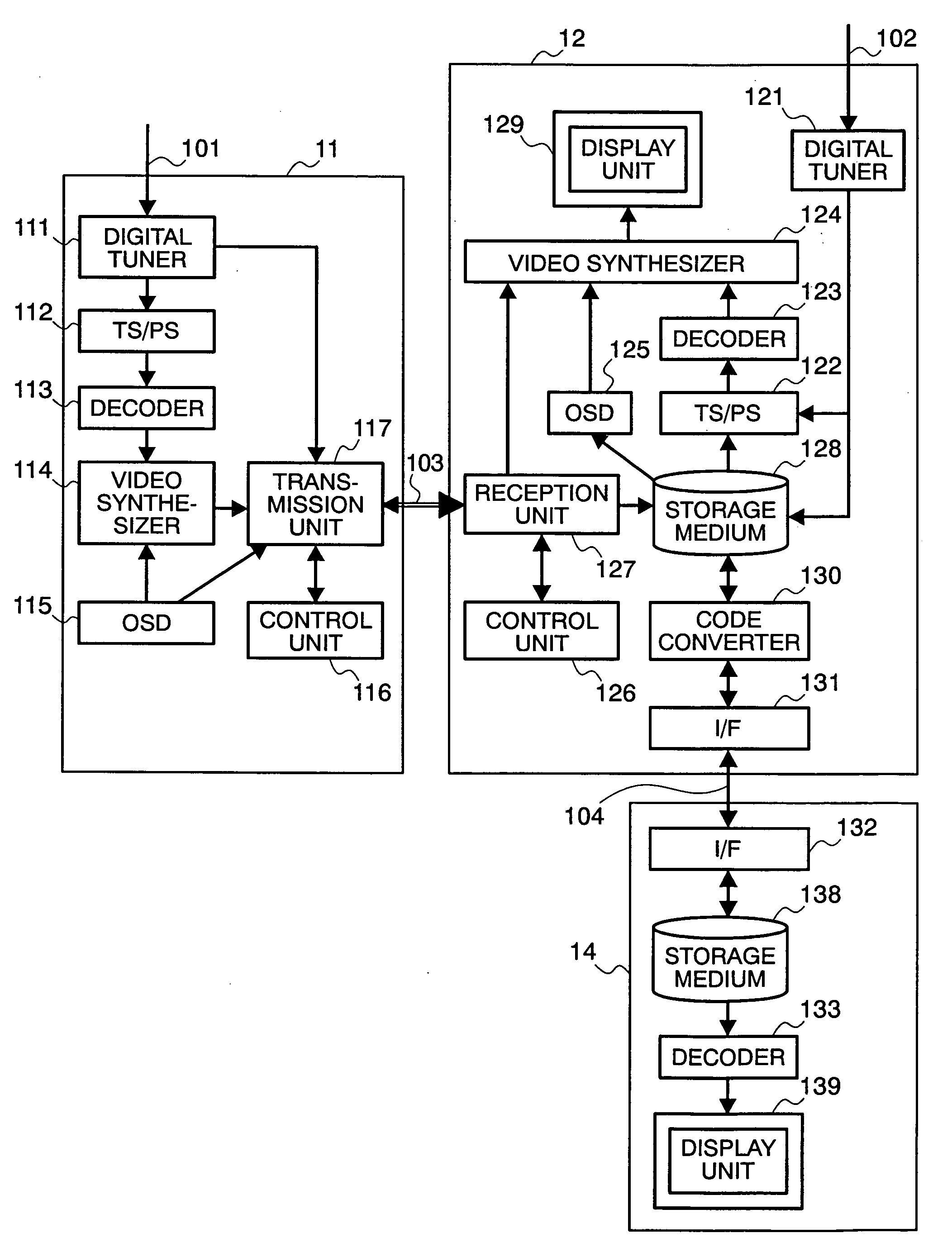
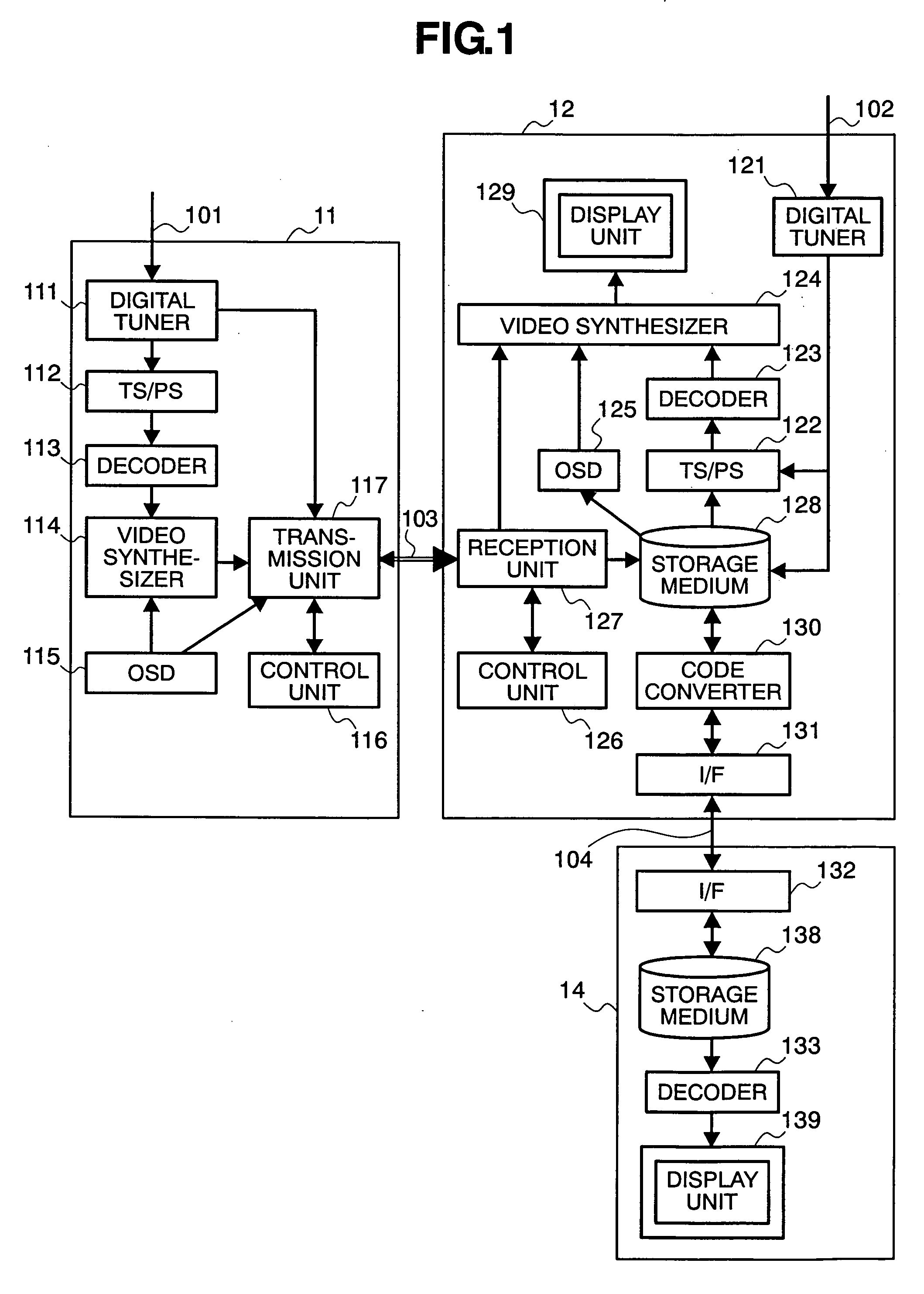
[0027]FIG. 1 is a block diagram showing the first embodiment of the present invention. The first embodiment includes a set-top box (STB) 11 that is an example of a video processing system, a television 12 that is another example of the video processing system, and a mobile viewer 13 making it possible to view a picture in any place other than a home. Examples of actions to be performed by these pieces of equipment will be described below.

[0028] The STB 11 receives a radiofrequency signal 101 sent through digital broadcasting or over a cable. A digital tuner 111 demodulates a transport stream (hereinafter a TS) carried by a compressed video signal. A TS / PS converter 112 samples a program stream (hereinafter a PS) from the demodulated TS. A decoder 113 produces a non-compressed video signal. A video synthesizer 114 synthesizes the non-compressed video signal with an on-screen-display (OSD) screen picture produced by an OSD unit 115. The non-compressed video signal is...

Example

Second Embodiment

[0046]FIG. 4 is a block diagram showing another embodiment of the present invention. In the present embodiment, the transmission unit 117 and reception unit 127 included in the system configuration shown in FIG. 1 are replaced with a transmission unit 230 and a reception unit 250 respectively shown in FIG. 4. In the present embodiment, the transmission unit 230 and reception unit 250 are interconnected via an interface including three data lines 271, 272, and 273 over which a video signal is transmitted and a clock line 274 over which a clock is transmitted. The three data lines are used to transmit respective non-compressed video signals of, for example, red, green, and blue. The clock line is used to transmit a reference clock synchronously with which data or a video signal is received. Moreover, ten data items shall be transmitted over the data lines during the cycle of the clock that passes through the clock line. Multiplex encoders 231 to 233 and 235, output c...

Example

Third Embodiment

[0050]FIG. 5 is a block diagram showing another embodiment of the present invention. The present embodiment has the same system configuration as the one shown in FIG. 1 except that the transmission unit 117 and reception unit 127 are replaced with a transmission unit 240 and a reception unit 260 which have the same configurations as those shown in FIG. 4. The same reference numerals are assigned to components identical to those shown in FIG. 4. The present embodiment includes the PLL shown in FIG. 4 as a component. However, the PLL is not shown in FIG. 5 for brevity's sake. The present embodiment further includes an input circuit 255, a multiplex decoder 265, a multiplex encoder 258, and an output circuit 257 which are not included in the embodiment shown in FIG. 4.

[0051] In FIG. 5, when data is transmitted using a clock line, the data is not transmitted from the STB 11 to the television 12 but is transmitted from the television 12 to the STB 11. In an initial stat...


PUM


Abstract

The present invention is intended to permit both real-time display of a picture represented by a non-compressed video signal on a television and display of a picture represented by a compressed video signal at any desired time by simultaneously transmitting the compressed video signal and non-compressed video signal via one interface. An STB packetizes a compressed video signal, and multiplexes the compressed video signal and a blanking signal combined with a non-compressed video signal. Thus, both the video signals are transmitted simultaneously. A picture represented by the non-compressed video signal is displayed on a television in real time. The compressed video signal is stored in a storage medium incorporated in the television, read at any user's desired time, and decoded so that a picture represented by the compressed video signal can be viewed at the user's desired time.

Description

BACKGROUND OF THE INVENTION [0001] 1. Field of the Invention [0002] The present invention relates to a transmission method for a digital video signal, and a video processing system, for example, a set-top box (STB) that receives a digital television signal or a television display device. [0003] 2. Description of the Related Art [0004] Along with both the prevalence of high-definition (HD) televisions (TV) reaping the benefit of digital terrestrial broadcasting and the sale of Blu-ray recorders capable of recording high-definition TV programs, the need for digital video interfaces via which a high-quality high-definition video signal is transmitted to televisions without deterioration of picture quality has been increased these days. The standards for interfaces supporting transmission of a non-compressed video signal include the digital visual interface (DVI) standards which are formulated by the Digital Display Working Group (DDWG), and the high-definition multimedia interface (HDM...

Claims


Application Information

Patent Timeline
IPC IPC(8): H04N11/02H04N11/04H04N7/12H04B1/66G11B20/10H04J3/00H04N7/167H04N7/173H04N19/00H04N19/44H04N19/467H04N19/65H04N19/88H04N19/89H04N21/2365H04N21/4147H04N21/436
CPCH04N7/088H04N21/4263H04N21/4325H04N21/4332H04N21/4334H04N21/4385H04N21/4347H04N21/4104H04N21/4147H04N21/42615H04N21/437H04N21/4344H04N21/43074H04N21/411H04N21/4307H04N21/4122H04N21/4348H04N21/43615
Inventor KABUTO, NOBUAKISHIBATA, AKIRAMIZUHASHI, YOSHIAKI
Owner MAXELL HLDG LTD
Why Eureka
Try Eureka