
Method and Apparatus for Material Identification

a material identification and material technology, applied in the field of methods for identifying materials, can solve the problem of impracticality of direct measurement of spectra from all candidates, and achieve the effect of reducing the solid angle subtended by the detector

Active Publication Date: 2006-12-28
OXFORD INSTR NANOTECH TOOLS
View PDF13 Cites 53 Cited by
  • Summary
  • Abstract
  • Description
  • Claims
  • Application Information

AI Technical Summary

Benefits of technology

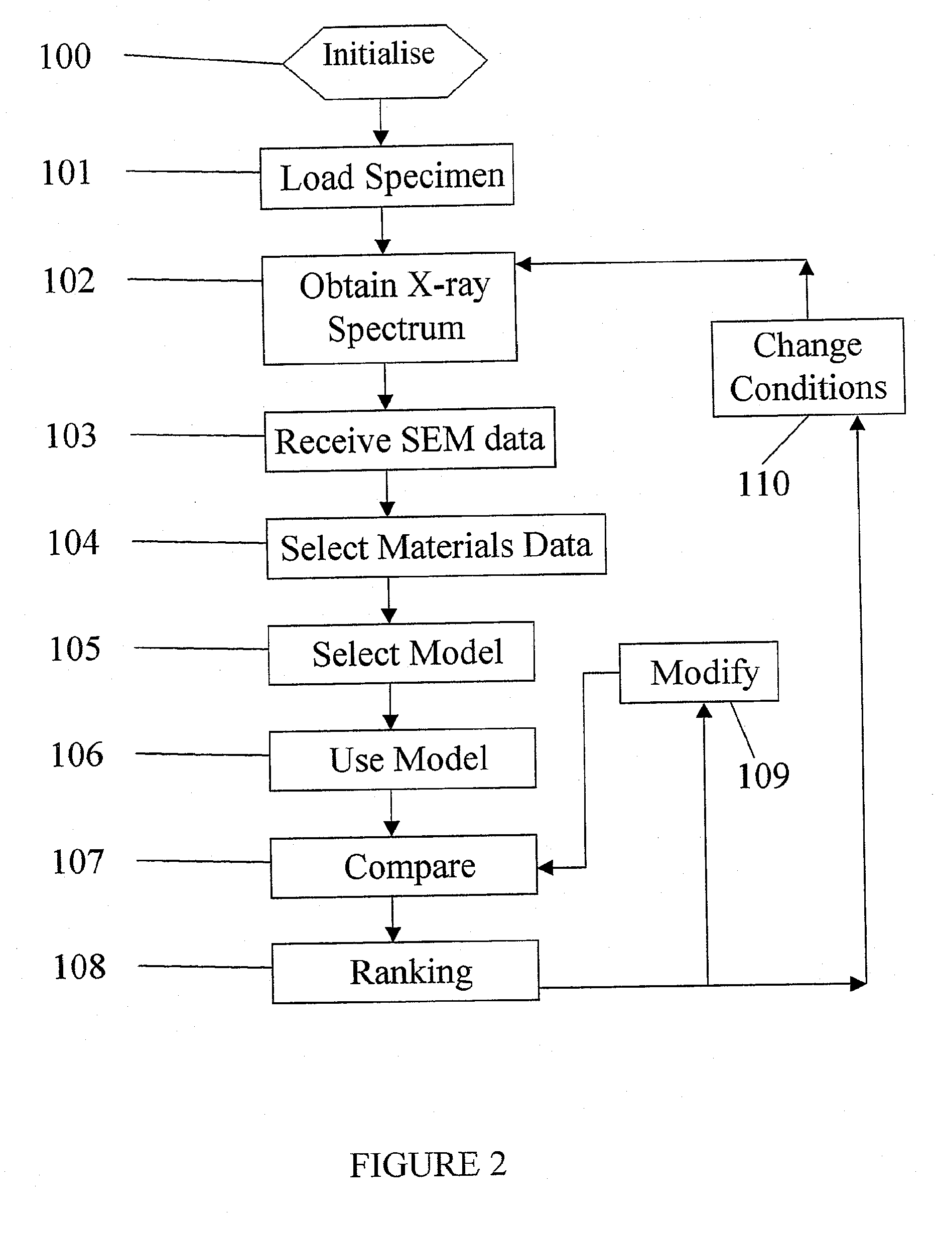
The present invention provides a method for identifying materials using x-ray emission characteristics. The method involves obtaining x-ray data of a specimen in response to an incident energy beam, and calculating predicted x-ray data for a set of materials using a database of composition data. The predicted data is then compared with the obtained data to determine the likely identity of the material of the specimen. The method allows for the identification of materials even when there is no standard material available for comparison. The accuracy of the predicted data is important, so the method includes validating the accuracy of the calculation method and adjusting the method accordingly. The method can be used even when there is no prior art data available for comparison. The method can be used with various detectors and can be calibrated based on the analytical conditions and the detector used. The method provides a way to identify materials using x-ray emission characteristics with high accuracy.

Problems solved by technology

As a result, spectral matching can be used to identify materials even when there is no reference material available or the number of candidate materials is so large that direct measurement of spectra from all candidates would be impractical.

Method used


Image

  • Method and Apparatus for Material Identification
  • Method and Apparatus for Material Identification
  • Method and Apparatus for Material Identification

Examples


example 1

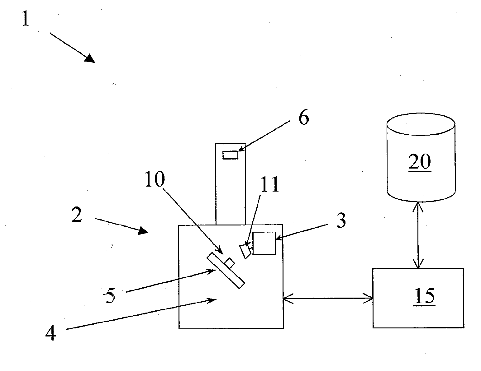
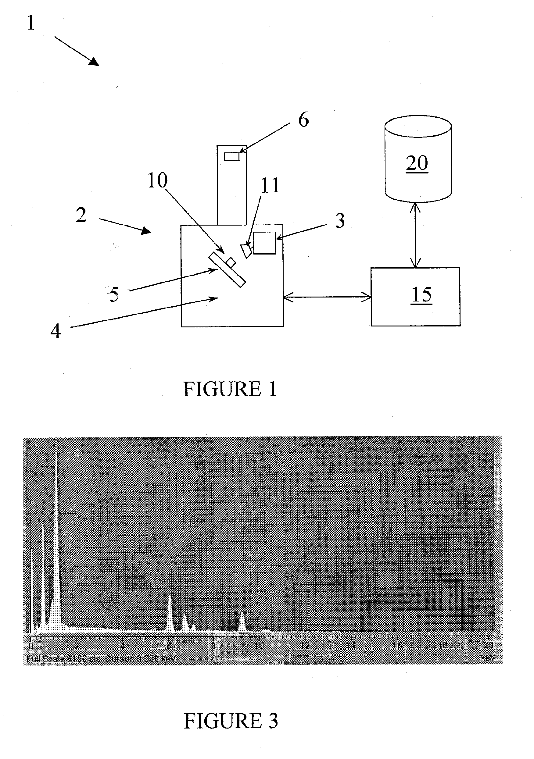
[0067] In this first example, a sample of Gd3Ga5O12 with surface at approximately 70 degree surface tilt is placed in the electron microscope 2 using a 20 kV accelerating voltage and the spectrum is recorded using the Oxford Instruments Analytical Limited INCA Energy x-ray analysis system 3. A Si(Li) detector with approximately 133 eV resolution at 5.9 keV and an elevation angle of 35 degrees is used and records an x-ray energy spectrum as shown in FIG. 3.

[0068] The chemical formulae for all 63,000 entries in the Inorganic Crystal Structure Database (ICSD) (J. Res. Natl. Inst. Stand. Technol. 101, 217 (1996) is used as the dataset of candidate material compositions. Each chemical formula gives atomic proportions that are converted to mass percentage of elements in the material. A spectrum synthesis program (based on “Improved X-ray Spectrum Simulation for Electron Microprobe Analysis”, Peter Duncumb, Ian R. Barkshire, Peter J. Statham, Microsc. Microanal. 7, 341-355, 2001.)) is use...

example 2

[0071] In the second example, a spectrum from a sample of SrAlLaO4 is obtained using the same SEM 2 and acquisition conditions as for the first example. In this case, even though the incident electron beam energy is 20 keV the sample charges negatively under the electron beam so the DHL is reduced to about 6 keV as shown in FIG. 4.

[0072] Some elemental peaks such as SrKα 14.2 keV do not appear in the spectrum because the landing energy of electrons is below the critical excitation energy for these x-rays. Furthermore, the relative intensities for peaks that are excited are different than they would be if the sample were not charging. To find candidate materials that would show peaks in the spectrum at the same energy, irrespective of relative intensity, both measured and synthesised spectra are modified by replacing all channel counts in the vicinity of peaks by a suitable constant and channel counts elsewhere by 0. In this example, the peaks are detected by a “Top Hat” filter (“De...


PUM

PropertyMeasurementUnit
accelerating voltageaaaaaaaaaa
elevation angleaaaaaaaaaa
critical excitation energyaaaaaaaaaa

Abstract

A method of identifying a material using an x-ray emission characteristic is provided. X-ray data representing a monitored x-ray emission characteristic is obtained from a specimen in response to an incident energy beam. A dataset is also obtained, this comprising composition data of a plurality of materials. The material of the specimen is contained within the dataset. Predicted x-ray data are calculated for each of the materials in the dataset using the composition data. The obtained and the predicted x-ray data are compared and the likely identity of the material of the specimen is determined, based upon the comparison.

Description

RELATED APPLICATIONS [0001] This application claims the benefit of GB Patent Application 0512945.7, filed Jun. 24, 2005. FIELD OF THE INVENTION [0002] The present invention relates to a method for identifying a material, together with corresponding apparatus and software for performing the method. BACKGROUND OF THE INVENTION [0003] In forensic analysis, semiconductor defect review, gunshot residue analysis and general materials analysis of alloys, ceramics, glasses, minerals, polymers and powders, the identity of a fragment of material can often be determined by collecting and analysing an x-ray energy spectrum. The x-rays can be excited from the fragment for example by a beam of x-rays (x-ray fluorescence, XRF) or electrons (electron probe microanalysis, EPMA) or protons (proton induced x-ray emission, PIXE). X-rays are often detected by an energy dispersive x-ray detector (EDX) which is typically a lithium drifted Si, Si(Li), detector or a silicon drift detector, SDD. For example,...

Claims


Application Information

Patent Timeline
Patent Type & Authority Applications(United States)
IPC IPC(8): G01N23/223G01T1/36G01N23/22
CPCG01N23/22
Inventor STATHAM, PETER JOHN
Owner OXFORD INSTR NANOTECH TOOLS
Learn More