
Corrosion-resistant coating for metal substrate

a technology of corrosion resistance and metal substrate, which is applied in the direction of manufacturing tools, solventing apparatus, transportation and packaging, etc., can solve the problems of limited use of cladding for protecting structural aluminum surfaces, structural aluminum alloys formed in more complex geometries, and corrosion resistance, so as to improve wear resistance, provide corrosion resistance, and high strength

Inactive Publication Date: 2006-12-28
BASF CATALYSTS LLC
View PDF11 Cites 20 Cited by
  • Summary
  • Abstract
  • Description
  • Claims
  • Application Information

AI Technical Summary

Benefits of technology

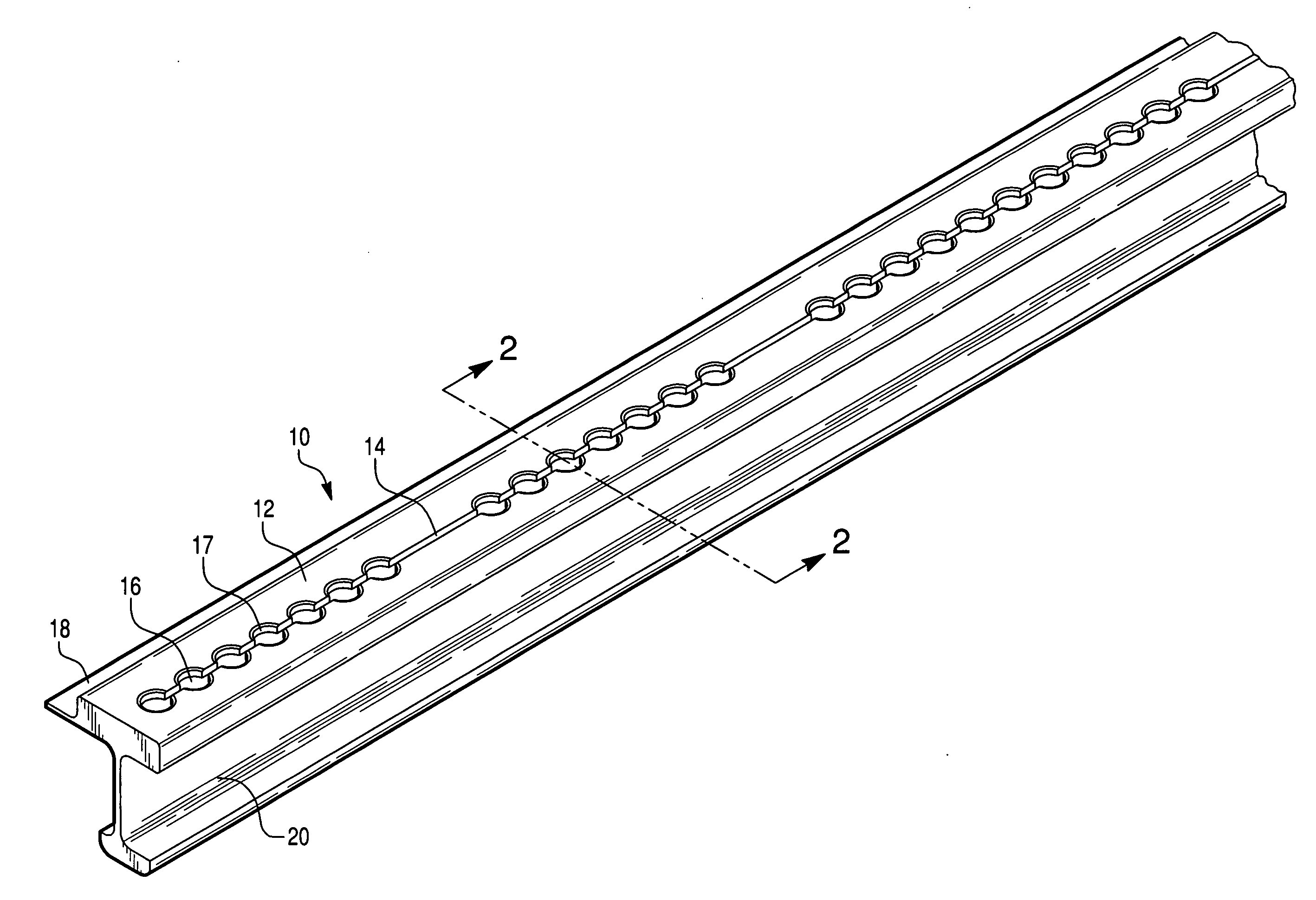
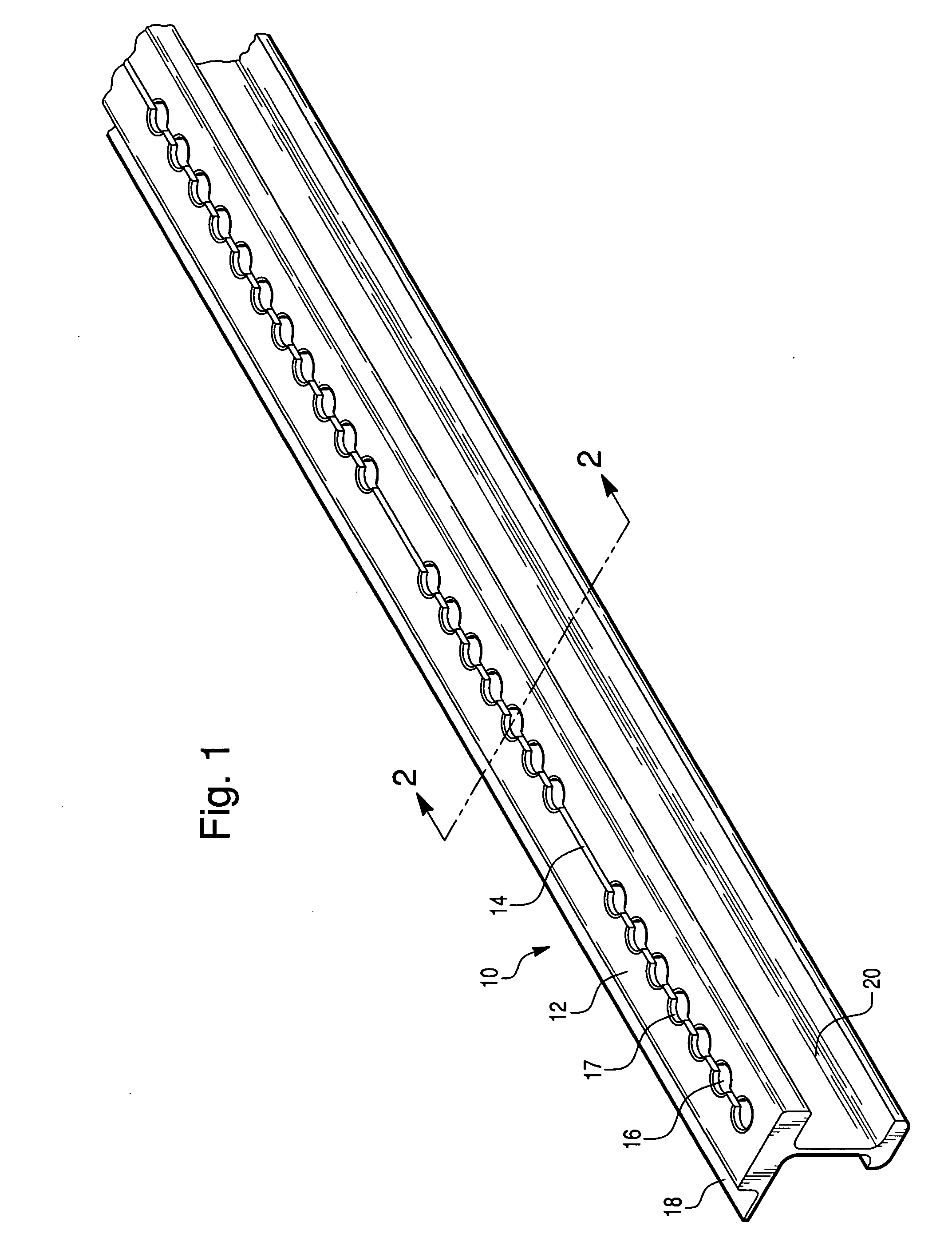
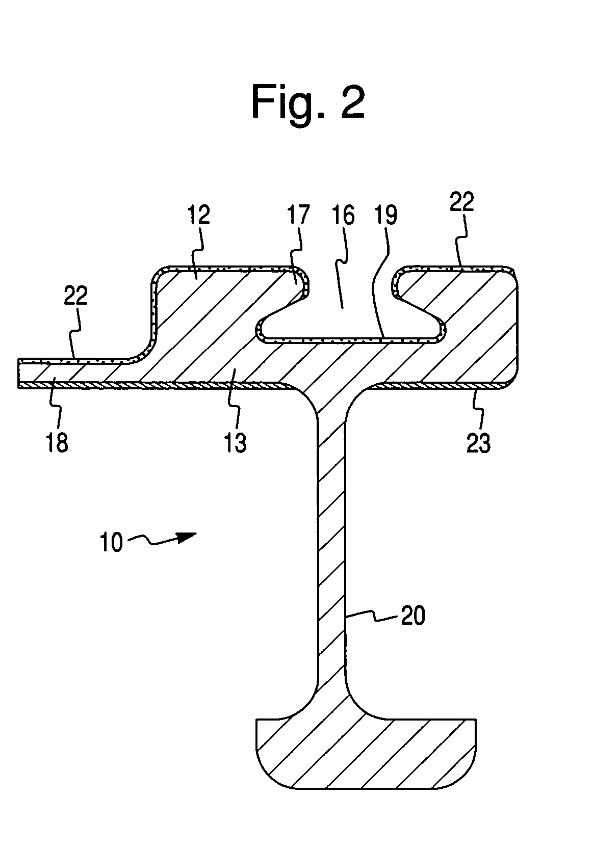
[0013] A novel coating composition is provided for imparting corrosion resistance to metal substrates. In accordance with this invention, the novel coating composition is thermally applied and comprises an aluminum-zinc alloy. To provide improved wear resistance, the aluminum-zinc alloy can be mixed with a ceramic or glass matrix. The coating composition has found particular use in providing corrosion resistance when thermally sprayed onto metal substrates that have complex multi-planar geometries that cannot readily be formed by metal rolling or stamping. Of particular interest is providing corrosion protection to metal seat rails used to secure aircraft seats to the aircraft frame. Such seat rails are typically formed of an extruded high strength aluminum alloy.

Problems solved by technology

While such alloying metals provide increased strength to aluminum, the result is an aluminum alloy which is now less resistant to corrosion.
While aluminum cladding has been used extensively to provide corrosion protection to underlying higher strength aluminum alloys, the use of the cladding is limited to protection of structural aluminum surfaces which are essentially configured along a single plane, e.g. sheeting.
Structural aluminum alloys formed in more complex geometries such as those having multi-planar surfaces and which cannot be formed by a rolling or metal stamping process cannot be covered with the protective aluminum cladding.
Porosity is high andcohesive strength is low.
A spark ignites the mixture and produces acontrolled explosion.
Porosity is the largest source of coating failure and is usually indicative of poor coating cohesion and a high degree of unmelted or cold-particle entrapment.
During the process of manipulating the seats along the rail to the desired position during installation, reconfiguration, and removal, the groove on the upper surface of the seat rail can get worn.
Additionally, vibrations during flight result in constant movement of the seat with the interlocking member against the groove of the seat rail, causing additional wear.
Likewise, metal surfaces of the seat rail that are exposed to the environment can corrode due to atmospheric conditions within the plane.
Corrosion due to standing water is prevalent.
Corrosion is also observed on all areas of contact between the seat rail and the seat legs where moisture can ingress into mating aluminum surfaces.
With the presence of moisture, galvanic effects between the seat rail, interlocking member, and the metal framing to which the seat rail is attached can also cause chemical corrosion along the rail.
Gaps in the corrosion protection, however, include, but are not limited to, all mechanical damage and fastener locations.
Corrosion has been found to occur on multiple areas of the seat track and is not always located on corrosion barrier gaps.
However, it has been found that the coatings previously used for seat rails, in particular aircraft, have not been sufficient to prevent wear within the groove of the seat rail, or to prevent corrosion effects on exposed metal surfaces of the seat rail.

Method used


Image

  • Corrosion-resistant coating for metal substrate
  • Corrosion-resistant coating for metal substrate
  • Corrosion-resistant coating for metal substrate

Examples


example 1

[0026] A coating composition is prepared comprising 50 vol. % of a powder mixture containing 97 wt. % aluminum particles and 3 wt. % zinc particles, and 50 vol. % of an alumina powder having an average particle size of about 500 microns. The composition is sprayed onto 4-inch by 4-inch aluminum panels by HVOF spraying at a flame temperature of 5,000° F. and a coating rate of 7 lb / hr. The nozzle is spaced 1.5 feet from the panels. A hard, dense, and smooth coating results on the panels.

example 2

[0027] Particles of an aluminum alloy comprising 98 wt. % aluminum, 1.5 wt. % manganese, and 0.5 wt. % copper are mixed with a ceramic powder comprising 85% silicon carbide and 15% silicon nitride. The ceramic has a particle size ranging from about 100-1,000 microns. The ceramic powder comprises 40 vol. % of the coating mixture. The coating mixture is applied onto 4-inch by 4-inch aluminum panels using HVOF spraying at a flame temperature of 5,000° F. and a coating rate of 20 lb / hr. The spray nozzle is placed 1.5 feet from the aluminum panels. A dense, hard coating results.

example 3

[0028] A coating composition is fed to an HVOF thermal spraying device for coating 4-inch by 4-inch aluminum panels. The coating composition comprises an aluminum alloy precursor comprising 95 wt. % aluminum particles and 5 wt. % zinc particles. A matrix comprising 95% alumina and 5% silica makes up 40 vol. % of the coating composition. The matrix component comprises particles ranging in size from 50 microns to about 750 microns. The aluminum panels are provided with an even, hard, dense coating. The aluminum particles and the zinc particles form an alloy during the spraying process.


PUM

PropertyMeasurementUnit
wt. %aaaaaaaaaa
temperaturesaaaaaaaaaa
pressuresaaaaaaaaaa

Abstract

A novel coating composition is provided for imparting corrosion resistance to metal substrates. The novel coating composition is thermally applied and comprises an aluminum-zinc alloy. The coating composition has found particular use in providing corrosion resistance to aluminum containing metal seat rails used to secure aircrafts seats to the aircraft frame.

Description

[0001] This application is a continuation-in-part of U.S. Ser. No. 10 / 973,502, filed Oct. 26, 2004.FIELD OF THE INVENTION [0002] The present invention is directed to a novel coating composition to be applied by a thermal spray process and a metal substrate coated with the novel coating composition to provide the substrate with corrosion resistance. The invention is particularly concerned with a metal seat rail for supporting aircraft seats and which is provided with the thermally applied novel corrosion-resistant coating. BACKGROUND OF THE INVENTION [0003] The application of corrosion-resistant coatings to metal articles in order to protect the surfaces thereof from degradation by oxidation, galvanic, or other chemical attack is a vastly important field of study. Much effort has been devoted to extending the useful life of articles subject to corrosion by coating the article with a corrosion-resistant composition. Coatings are also applied to substrates for protection against physic...

Claims


Application Information

Patent Timeline
Patent Type & Authority Applications(United States)
IPC IPC(8): B32B15/00H05H1/26B05D1/08
CPCB23K35/286B32B15/01C22C21/10C22C32/00Y10T428/12799C23C4/06C23C30/00Y02T50/67B64C1/20C23C2/04B32B15/00B05D1/08Y02T50/60
Inventor FRONING, MARC J.RUGGIERO, PETER F.
Owner BASF CATALYSTS LLC
Learn More